Abstract
Concrete structures are usually subjected to unfavourable environments that reduce their durability. For example, chloride penetration is one of the main types of environmental attack that damages buildings, monuments and reinforced concrete bridges. Chloride ingress corrodes reinforced concrete structures thereby reducing their strength and durability. The aim of this thesis was to investigate construction practices affected by salinity and how to combat or eliminate the effects of salinity. This thesis adopted a case study approach in investigating the effects of construction in saline environments. Two cases were used to shed light on the topic under study.
First, the researcher analysed the effects of salinity on different stone samples collected in the coastal region of SW France. Second, the researcher investigated the effects of salt attack on examining seven concrete bridges located around Goteborg, Sweden. Specifically, the researcher focused on the chloride penetration, concrete cover, and visible signs of reinforcement corrosion in these bridges. Several strategies to combat salinity in buildings were also discussed. For instance the researcher discussed the role of damp-proof course (inserted beneath the concrete slab) in averting chloride penetration in buildings found in saline environments. The researcher concluded that, indeed, salinity is one of the major causes of concrete disintegration and reduces the durability of buildings in saline environments.
Introduction
Concrete structures are usually subjected to unfavourable environments that reduce their durability. For example, chloride penetration is one of the main types of environmental attack that damages buildings, monuments and reinforced concrete bridges. Chloride ingress corrodes reinforced concrete structures thereby reducing their durability. Such an attack can result in premature repair or early replacement of the structure. Thus, it is important to use impenetrable concrete in order to prevent chloride ions from penetrating the building and causing damages. However, chloride ions take time to penetrate and cannot be detected easily. Thus, it is important to adopt a test measure that speeds up the process and permit the establishment of diffusion values in a short time (Stanish, Hooton & Thomas 1996).
A landscape is deemed saline if it has a high concentration of salt. There are many types of salts that can cause salinity although the most common one is the table salt or sodium chloride. It is worth mentioning that salts can form in many places. Besides, water and wind are the main agents that transfer salts from one landscape to another. For example, urban salinity occurs when the groundwater rises to the land surface, carrying along salt compounds. Some urban centres are found in areas susceptible to salinity. Although salinity is principally caused by the rise in the groundwater level, urban development can also increase the level of salts in the landscape. For example, urban salinity can happen under the following conditions:
- Native vegetation is cleared to pave way for urban development
- Water leaking from drainage systems and tanks
- When sporting fields, parks and gardens are over-watered
- Discharge from silage pits
- Altering or obstructing natural drainage paths (i.e. During road construction)
The disastrous effects of salinity are not confined to those regions where the groundwater level is rising. Many buildings can potentially be damaged by ordinary localized problems including blocked sewer lines and leaking taps or downpipes. For example, these localized problems can surface when air-conditioning systems are installed adjacent to the buildings. The water that is discharged from air-conditioning drainage pipes usually flows onto nearby lawns or garden beds. Thus, a building is highly susceptible to salt attack if one of these ostensibly harmless water sources is present. In other words, any water source can potentially instigate salt attack on a building.
It is against this background that the following section documents the aim and objectives of this research.
Scope and Objectives
The ultimate purpose of this study is to offer a comprehensive paper on all the construction practices affected by salinity and how to combat or eliminate the effects. Upon completion, It is expected that professionals in any filed will use this research paper in their design and construction processes. Ultimately, the specific objectives of this research paper are:
- To identify the main problems associated with construction that takes place in saline environments using research material and relevant case studies.
- To break down these problems based on the construction process it affects, for example the effect on concrete, the effect on the bricks and the effect on road construction.
- Demonstrate how to eliminate the effects of salinity by illustrating correct methods of construction and how to combat the effects if they have already appeared.
Assumptions
This study will be based on the technical and the non-technical assumptions in an attempt to achieve the purpose and objectives of this paper.
Key Technical Assumptions
- Salinity is indeed a problem in the construction industry
- Salinity can be resolved with good design and construction practice
Nontechnical Assumptions
- The findings of this paper will make the society safer by highlighting the possible dangers of excluding salinity in the design and construction process.
- Although initial costs may be higher, it will be more economical in the long run to implement the suggested design and construction methods.
Organization of the Thesis
Chapter 2 aims to define and explore any technical areas relating to this thesis, namely, the effects of salinity on buildings. This chapter reviews the theories both empirical and theoretical that are closely linked to saline environment and its impact on the construction materials. The chapter also explores a number of measures that have been used to prevent the adverse effects of salts on houses and buildings.
Chapter 3 will discuss practical work and experimentation. This chapter will analyse two case studies that are relevant to the topic at hand. First of all, chapter 3 will analyse how salinity has affected concrete samples obtained from the coastal region of southwest France. Special attention will be directed to the manner in which salts from marine accumulate in buildings and monuments found in this coastal region of France. To be precise, this chapter will investigate how chloride ions are transported into the concrete and the resultant outcomes. The main samples that will be analysed are La Pallice stones and decayed Crazannes stones. Second, this chapter will investigate the effects of salt attack on examining seven concrete bridges located around Goteborg, Sweden. Specifically, this chapter will focus on chloride penetration, concrete cover, and visible signs of reinforcement corrosion in these bridges.
Chapter 4 will discuss the presence of various types of salts found in Crazannes stones and La Pallice stones. It will also discuss several salt damage mechanisms (i.e. Chemical weathering and hydration pressure) in these stone samples. The role of salt spray in the weathering mechanism will also be discussed. What is more, the chloride penetration in the seven bridges will be discussed in detail. Finally, this chapter will discuss a number of factors that must be taken into consideration in order to construct durable buildings and bridges in saline environments. It will also discuss strategies that can be adopted to prevent the penetration of salt and water into the buildings.
Chapter 5 will present the major conclusions contained within this thesis. It will also present recommendations on the strategies that can be adopted to combat saline damage and construct durable buildings in saline environments.
Chapter 6 suggests areas that should be investigated by future studies to collect further information which could be used to augment the findings of the current thesis.
Literature Review
Introduction
This chapter reviews the theories both empirical and theoretical that are closely linked to saline environment and its impact on the construction materials. The chapter also explores a number of measures that have been used to prevent the adverse effects of salts on houses and buildings.
Types and origin of salts
Although deeper understanding of salt geology and chemistry may not be necessary, the information will be useful during the study. Salinity refers to existence of salt in an environment (O’Caoimh, 2007, p. 8). These salts may originate from rocks, oceans /seas, or transported by wind. During the weathering process rocks are normally subjected to physical and chemical processes which prompt the release of salts. Ocean/sea salts also do find their way inland through rainfall, winds, and tides. It is estimated that the ocean/sea salt can be deposited up to 600 kilometres inland. In addition, there are cases where salts are left behind after lakes or sea have retreated or evaporated. These salts have mixed with other soil particles to form dusts which have been blown by wind for centuries (O’Caoimh, 2007, p. 9).
Chlorides salt results from chemical reaction between chlorine and different sets of metals. These salts have a corrosive effect on metals (Melchers, & Lawanwisut, 2008, 447). On the contrary, chlorides are very important for growth and development of animals and plants. Some of the widely known chlorides are sodium chloride and magnesium chloride. Most of these chlorides originate from the sea water, animal waste, septic system and potash fertilizers (Haynes et al., 2010, p. 259).
On the other hand, sulphate salts contain sulphate ion. Examples of sulphate salts include gypsum, Celestite and baritite. Sulphate salts are mostly found in natural water, urban sewage and industrial effluent. Nitrate salts originate from the breakdown of nitrogen compounds in the soil and therefore are common in ground water. Other sources of nitrate salts include nitrogen fertilizer, animal waste, industrial and urban waste, and plant remains (O’Caoimh, 2007, p. 9).
Salinity process and concerns
Salinity is a major problem that afflicts most buildings found in urban areas. The urban salinity is largely attributed to the rising subterranean water which brings salts to the surface. This is common in areas prone to salinity such as coastal strips, plains, and valleys among others (Beeby 1978, p. 4). O’Caoimh (2007, p. 10) Urban development can also cause localized salinity. This is attributed to clearance of native vegetation, overwatering of the parks and gardens, leaking of pipes, seepage of silage pits, and blockage/alteration of the natural drainage system. Water from these sources has the capability of consolidating salt on the building sites. Therefore, the effect of salinity in the urban areas is not restricted to the zones of rising water tables (O’Caoimh, 2007, p. 11).
Urban salinity is an intricate subject which involves mobilization, redistribution and concentration of salts in an urban environment and their resultant effect. Urban salinity has degraded urban infrastructure to an extent that governments are forced to spend massively on repair work and untimely replacement (Sergi, Yu & Page, 1992, p. 63). Similarly, houses and other buildings have been and continue to be degraded by the harmful impact of salinity. The impact of the urban salinity on these buildings is normally significant and occurs in a relatively short period of time (O’Caoimh, 2007, p. 12).
Experts argue that the level of salt present on the building location or materials is normally not high enough to cause considerable damage to the buildings. However, the problem normally arises when the concentration of these salts increased with time (Sergi, Yu & Page, 1992, p. 64). The concentration of these salts generally results from a series of cycles commonly known as the salt cycle. Salts are generally present in moving water and when the water evaporates salt remains and re-crystallize. As soon as the extra solutions are introduced it dehydrates and remobilizes the existing salts. Therefore, the salt cycle ensures salt redistribution and concentration (Mehta, 1991, p. 12). The rate of recurrence of the salt cycle depends on the amount of water available, the speed at which the solution gets in the zone of evaporation, and the evaporation rate. Therefore, the cycle may be continuous or intermittent depending on the availability of water (O’Caoimh, 2007, p. 12).
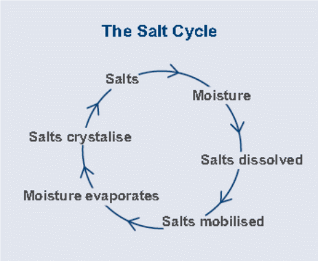
Movement of saline water
As mentioned above salt crystals dissolve in water. When this takes place the salts are said to be mobilized since they can move around houses and other buildings in solution. The water sources can either be either internally or externally (Mehta, 1991, p. 12). The three main processes through which water moves around buildings are rising damp, horizontal damp, and feeling damp (O’Caoimh, 2007, p. 23). The first process (rising damp) occurs when capillary pores (in the concrete) facilitate the transportation of water into the buildings. The pores in concretes and bricks acts as fine tubes and are estimated to hold up to one meter high column of water. The presence of salt increases the surface tension and as a result enhances the water column thus achieves a greater height of dampness. Introduction of new water into the building material irrespective of the level of salt concentration can also mobilize the existing salts (O’Caoimh, 2007, p. 23).
Horizontal damps take place when leaked water is absorbed by the building materials. Dampness resulting from horizontal damp is normally restricted to the source of water. The leakage can be from the sink pipes, down pipes, shower, and waste pipes among others (O’Caoimh, 2007, p. 24). Dew deposits and rain splash can also cause horizontal damping. Buildings and structures located along the coastal strip often experience sea spray. Lastly, falling damp takes place where water from the domestic sources are allowed to flow into the building. These waters move either through capillary action or through gravity (O’Caoimh, 2007, p. 25).
Impact of salt on building materials
Salts normally cause physical and chemical damage to buildings. The level of chemical damage is highly correlated with the level of salt concentration, type of salt present, and the types of the building material (Sathiyanarayanan et al., 2006, p. 634). On the other hand, physical attacks depend on the frequency of the salt cycle. Highly frequent salt cycles enhance the formation of larger salt crystals. When subjected to high temperatures, these salts enlarge causing cracks to emerge in the affected buildings (Kawano, Watanabe & Koga, 2001, p. 96). The level of physical damage depends on the location of salt crystal on the building material, in addition to the physical conditions and the strength of the building material. The destruction effect of the salt crystals within the building materials can be rather shocking (Haynes et al., 2010, p. 260).
Long term exposure to salts also has adverse effects on the building components (Kawano, Watanabe & Koga, 2001, p. 93). Although the most affected components are always concrete structures and masonry members, salt exposure also affects painted surfaces, water pipes and fittings, vegetations, and other metallic structures. The physical attack on the building component normally compromises the building standard (Nilsson et al., 2000, p. 4).
Effect of salt on the brickwork and mortar
Many studies have established that the evaporation rate in brick walls is normally higher on the outside than on the inside (O’Caoimh, 2007, p. 30). However, the evaporation rate is higher on the side facing the sun mostly the north facing wall. Higher level of evaporation accelerates salt cycle and as a result increases salt concentration. Higher concentration of salt translates to more damage. The salt cycle will always continue as long as the conditions are favourable (more supply of salt and water) (O’Caoimh, 2007, p. 31).
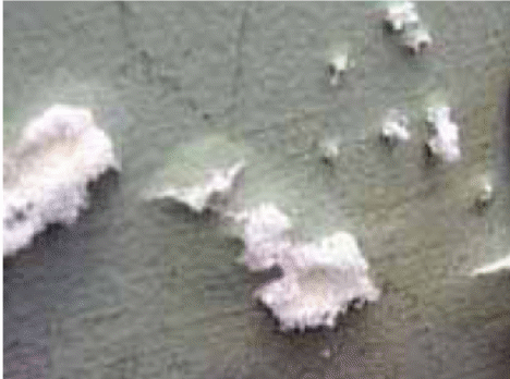
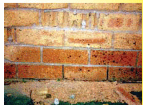
The considerable damage to the bricks and other components normally occur over a long period time and is a result of continuous salt cycle. However, there are documented reports on brick failures as a result of excessive exposure to saline environment in less than a year (Sergi, Yu & Page, 1992, 63). During high temperatures, the salt crystals expand and peel off the exterior section of the brick. The removal of the outer surface increases the brick’s surface area which in turn increases the rate of evaporation consequently resulting in the exposure of the internal parts (Melchers, Li & Lawanwisut, 2008, 450). The peeling off of the brick layers as a result of the exerted force of the salt crystals is commonly referred to as fretting. The damaged parts if left unattended to could have serious repercussion on the brickwork and masonry component (Sergi, Yu & Page, 1992, 65).
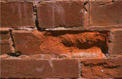
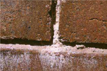
The effect of salt on mortar depends on its permeability. Salt can also accumulate in the joints of permeable mortars and masonry components. Although the masonry components can endure the effects of salts, the mortar grains are normally removed from the pressure exerted by the salt crystals during hot weather. Nearly all countries have a building code that details the suitable mortar and masonry unit mix (O’Caoimh, 2007, p. 26).
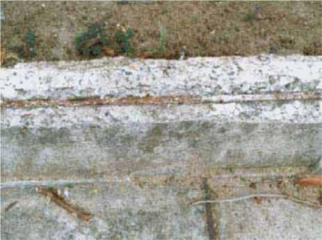
Effect of salt on concrete and painted surface
There has been a lot of interest among the engineers on the impact of saline environment on reinforced steel. According to the experts salts in dry state have no significant impact on the concrete (Melchers, Li & Lawanwisut, 2008, p. 447). However, when the crystals dissolve in water, they can have a devastating effect on the concrete structures. The impact of the salt solution to the concrete structure depends on the concrete component and the treatment of concrete. The impact is also high in highly permeable concrete. Similar to break and mortar, permeable concrete enables larger salt crystals to accumulate in between the grains. The expansionary forces exerted by these crystals during the dry phase of the salt cycle may cause startling damage (Sathiyanarayanan et al., 2006, p. 631).
An additional effect of salt on concrete is the rusting of the metal reinforcements. Rusting may reduce the strength of the concrete structure. The expansionary forces produced by the rusting metal may also cause additional physical damage to the concrete structure (Sathiyanarayanan et al., 2006, p. 631). The permeability of the concrete can be minimized by increasing the cement to water ratio. Higher cement to water ratio ensures compaction and therefore removes air spaces. Permeability can also be minimized through curing of the concrete. Concrete curing ensures that the concrete components form a strong bond which enhances the strength of the concrete structure (Melchers, Li & Lawanwisut, 2008, p. 448).
According to Sathiyanarayanan et al. (2006, p. 632), corrosion of steel bars is the major reason for damage and failures in majority of reinforced concrete structures. Salt increases the rate of corrosion in most metals and therefore plays an important role in the damage and failure of most of the reinforced concrete structures. Numerous studies have explored the durability problems of reinforced concrete structures resulting from exposure to saline environment. Most of these studies have focused too much on the chloride salts (Melchers, Li & Lawanwisut, 2008, p. 449).
According to Sergi, Yu and Page (1992, p. 64), accumulation of chloride in a reinforced steel is likely to catalyse corrosion except for environmental conditions that are highly anaerobic. Studies also show that critical concentration must be surpassed for the initiation of the corrosion process. These studies also established that the permeability of the concrete structure also plays a major role in the corrosion process (Sergi, Yu & Page, 1992, p. 65).
There have been a growing tendency of applying paints and other coatings on surfaces that are below the damp proof course especially among the new buildings. The exposure of these surfaces to salt may have a devastating effect. The negative effects can be felt even in a short span (Melchers, Li & Lawanwisut, 2008, p. 448). On the other hand, coating may interfere with the salt cycle by minimizing permeability especially the water proof paints (Mehta, 1991, p. 6).
Averting the salt cycle
Sergi, Yu and Page (1992, p. 66) argues that the only way to prevent the adverse effects of salt on different structures is by breaking the salt cycle. The implementation of building practices and use of materials that can effectively and efficiently prevent water/moisture from entering the building is the key to averting salt cycle (O’Caoimh, 2007, p. 8; Melchers, Li & Lawanwisut, 2008, p. 452). Both internal and external sources of water/moisture principle agents in the salt cycle and therefore governments have come up with building standards that have helped in averting the salinity problem. In addition, there are laws that control the amount of salt that are introduced in the water bodies, land, and other materials. However, in some environment salts are already present and therefore attempts of controlling such salts is not practicable. Therefore, the only way of minimizing impact of salts on different structures is by tackling the moisture content (O’Caoimh, 2007, p. 9).
Another factor that contributes to salt cycle is the rate of evaporation. Among the principle variables that contributes to salt cycle, evaporation is the trickiest to tackle (Lindvall, 2001, p. 320). Engineers used to recommend the addition of sub floor ventilation to minimize evaporation on structural walls. The introduction of ground slab has led to the abolishment of this strategy (Melchers, Li & Lawanwisut, 2008, p. 455). Nonetheless, the most efficient measures of breaking the salt cycle is prevention of water/moisture from entering the buildings or structures (O’Caoimh, 2007, p. 33).
The most common measures of preventing water or moistures from getting into the buildings or structures include: putting a layer of sand beneath the slab to enhance drainage and reduce capillary action; placing a waterproof covering between the sand layer and the slab; use of class bricks beneath the waterproof membrane; placing the waterproof course beneath the concrete or brick work; and putting in place and maintaining a sound drainage system (O’Caoimh, 2007, p. 35).
Before laying a slab it is recommended that a layer of sand of over 50 mm should be placed first. The sand layer enhances the drainage and minimizes capillary action of the subterranean water/moisture. Therefore, sand layer acts as a supplementary barrier for sub-soil moisture (O’Caoimh, 2007, p. 35). The sand used is usually free of impurities. Besides enhancing underground drainage and capillary action, the sand layer also makes it easier to realize finished levels, to form beams, attain uniformity in slab depth, minimize damage to the waterproof membrane in advanced levels, and minimizes the cost associated with site preparation (O’Caoimh, 2007, p. 36; Stuart, 2012., p. 8). Damp proof membrane is always used in ground construction to avert moisture from reaching the slab. It is highly recommended to use high impact resistant membrane in saline environment (Stuart, 2012, p. 8).
As a mentioned earlier another way of breaking the salt cycle is by minimizing concrete permeability. This can be achieved by mixing coarse and fine particles, cements and other chemical additives improve the general property of the concrete. Normally concretes solidify through a series of chemical reactions which results in the formation of new compounds. The compounds interlock and bind all the components together. The more interlocking the stronger and more compact the concrete becomes (Stuart, 2012, p. 9). In addition, water plays an important role during the curing phase. However, too much water could negatively affect the curing process. In addition, excess water could create more pores in the concrete thus increasing porosity and permeability (O’Caoimh, 2007, p. 34).
The air spaces in the concrete can also be removed through compaction. This can be achieved by shaking or vibrating the concrete to allow trapped air to escape. The empty spaces are filled with concretes improving the bond through reinforcement. Compaction is normally carried out when the concrete is still plastic (Kawano, Watanabe & Koga, 2001, p. 95). According to the Australian building code curing process should take around seven days for constructions in the salinity prone environment. However, most literatures recommend at least three days for the curing process in a normal environment (Watanabe & Koga, 2002, p. 33; O’Caoimh, 2007, p. 37).
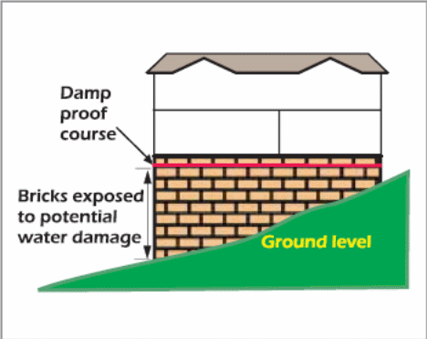
The building code of Australia also recommends the use of exposure grade bricks in the saline environment. These bricks are placed below the damp proof course especially in areas which are prone to salinity attack. In Australia these bricks have passed the Australian Standard AS4456. Bricks that have been certified are highly resistant to all types of salt (O’Caoimh, 2007, p. 37). However, bricks that are classified as general purpose bricks are not suitable to be used in saline environment or in areas where the building is prone to salt attack. General purpose bricks normally allows moisture and dissolved salts into the buildings/structures (O’Caoimh, 2007, p. 38). Figure 5 shows how exposure grade bricks are aligned in areas prone to salt attack. Exposure grade bricks are used below the damp proof course.
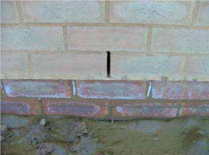
Damp proof course refers to recommended materials that are impermeable to moisture. The most common materials used in damp proof course include coal tar, slate, polythene sheet, and mortar containing chimney soot among others (Watanabe & Koga 2002, p. 57). According to the Australian building code, materials used as damp proof course must be certified under AZ/NZS 2904 standard. This standard was set because there were many reported cases where moisture had entered the building materials despite of the fact that the damp proof course had been laid. Nonetheless, the damp proof course does not provide 100% protection (see fig. 7) Since they are vulnerable to damage or breakage (O’Caoimh 2007, p. 44).
The Reaction of Salts with Construction Materials
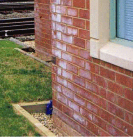
It is worth mentioning that several factors will determine the degree of the chemical damage in the materials used for constructing buildings in saline environments. They include: the nature of the construction material, types of salts absorbed, and their concentration levels. Conversely, physical damage occurs when the construction material is subjected to a wetting and aeration process. During dehydration, salts assume crystalline forms and apply physical pressure on the construction material. During rainy season, salt crystals are liquefied and transported by flowing water into the buildings. During the dry season, water evaporates from these buildings leaving behind high quantities of salt crystals in the interior sections of the building.
In many cases, when the rate of evaporation is extremely high (such as in a brick veer building), the concentration level of salt crystals in the walls of the building may increase dramatically and cause physical and chemical damage. What is more, the concentration of salts in the concrete structures of the building can increase if water (containing soluble salts) moves freely into the building. The negative effect of salts and water moving into the building is shown in figure 1 below. The high concentration levels of salt crystals cause the outer surface of the building to peel off. The surface area of the brick increases as more grains systematically remove the salt crystals. The rate of evaporation increases as more grains are peeled off. Consequently, the weaker interior of the brick is exposed (McGhie 2003).
The Reaction of Salts with Concrete
Concrete is formed when fine and coarse aggregates are mixed with cement and additives (i.e. Slag and fly ash) to boost its properties. It deserves merit to mention that the chemicals cannot damage concrete unless they are dissolved in the water. Nevertheless, once these chemicals are mixed with water, several physical and chemical reactions can take place. For instance, acids dissolve calcium hydroxide (found in concrete) to create soluble salts that can be percolated from the concrete thereby making it extremely porous and weak. What is more, the reaction between sulphate ions and calcium aluminate ions produces physical pressure on the concrete. The degree of the sulphate attack is subject to several factors including the solubility of various sulphates (figure 9). Generally, a chemical reaction between chloride ions and concretes happens rarely. Nonetheless, alterations in the temperature and humidity can lead to the development of salt crystals that impose physical stress on the concrete (McGhie 2003).
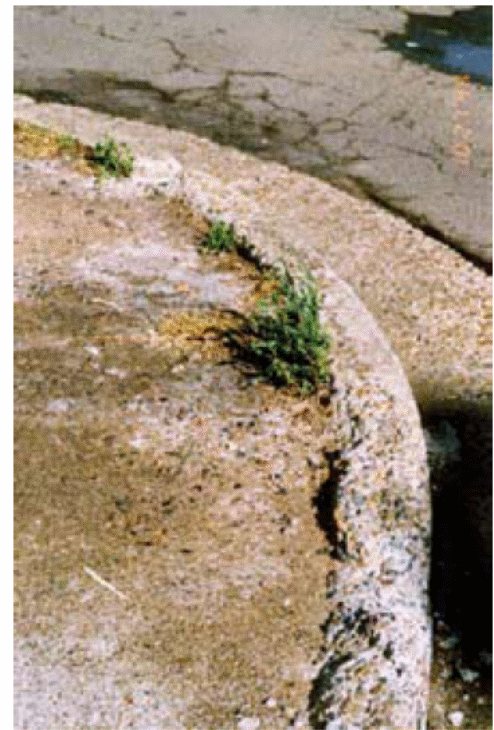
Corrosion of Reinforcement in Concrete
Generally, it takes place in two phases. For example, the first phase (known as the initiation phase) happens when the level of alkaline in the concrete reduce as a result of the carbonation process. There are various sources of carbonates. These include carbon dioxide and groundwater. What is more, higher chloride levels in concrete (from groundwater, acid etching and cement admixtures) results in ionization. The rate at which the propagation phase of the corrosion occurs is subject to several factors. These include the amount of moisture, oxygen and reactive ions available as well as the residual alkalinity (figure 10). Thus, it is vital to know the condition of the construction site as well as the types of chemical present. Such information will allow the selection of appropriate construction materials for use. What is more, the production of concrete and other construction materials on site should be done under careful supervision to ensure that the ultimate building can withstand the saline environment (McGhie 2003).
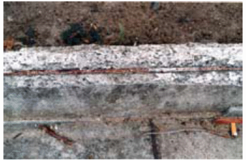
Sulphate Attack on Concrete
There are various factors that determine the durability of concrete in sulphate conditions. These include: the groundwater level, the type and concentration of sulphate, and the porosity of the concrete. Nonetheless, the sulphate attack on concrete is an intricate process that must be analysed carefully. For example, the process of sodium sulphate attack can be categorized into three groups. These are salt crystallization, gypsum formation and ettringite formation. The concrete can crack because the byproducts expand and cover more space than the original compounds. For instance, the volumes of ettringite and gypsum formation expand by approximately 2.4 and 1.2 times respectively. On the other hand, salt crystallization can cause the concrete to expand by approximately 4 times of the initial volume (Irassar, DI Maio & Batic 1996, p. 113).
Concrete with mineral admixture was frequently used for construction during the 1970s due the ecological and economical advantages. However, the mineral admixtures contribute to sulphate attack in various ways. For instance, they dilute C3A and reduce calcium hydroxide and permeability in concrete. Previous laboratory studies have shown that Portland cement can effectively resist sulphate attack if mineral admixtures are added. However, long term studies have lent credence on evaluating the adjustments in the fundamental engineering properties (i.e. Rigidity, strength, mass loss and expansion) and the role of mineral admixtures in concrete have been assessed on the basis of this limited information. It is important to mention that concrete is usually exposed to different conditions including drying shrinkage, superficial carbonation and variation in temperature. These conditions can determine the nature of the attack and it is widely acknowledged that they cannot be replicated in the laboratory (Irassar, DI Maio & Batic 1996, p. 113).
Salt Weathering in Calcareous Stone Monuments
Salt weathering occurs when a rock disintegrate under different conditions. Salt weathering is a common geomorphic procedure that weakens masonry and stonework used in architectural heritage around the world (figure 11). There are various sources of salts. According to Cardell et al (2003), these sources are greenhouse gasses, earth, seawater and moisture (p. 165). What is more, Cardell et al (2003) states that most of the buildings and monuments located in coastal regions suffer from salt attacks caused by marine aerosol (p. 165). The process of salt crystallization can bring about mechanical action that can tear down any stone (Cardell et al., 2003, p. 165).
Chloride Penetration in Roads
There are several factors that influence the road environment. These factors include the distance to the road, the nature and volume of traffic on the road, and the nature and volume of de-icing salts exposed to the road (Lindvall 2002). In addition, concrete road bridges are susceptible to chloride exposure in three main ways.
Aerosols from speeding vehicles
Speeding vehicles generate aerosols (spray) that percolate the road structure via air-streams. In other words, the chloride-polluted aerosol can penetrate some sections of the road structure that are not parallel to the direction of the traffic (Lindvall 2002).
Splash from Speeding Vehicles
Chloride can also penetrate concrete road bridge when splash (emanating from speeding vehicles) lands in some sections of the structure that do not face the direction of the traffic (Lindvall 2002).
Chloride Leakages through Joints
Chloride-polluted slush on the road surface may escape via joints and enter the base of the bridge slab causing damage (Lindvall 2002).
Theoretical Background
Processes of Chloride Ion Transport
There are three main ways through which chloride ion enters the concrete. They include diffusion, hydrostatic pressure and capillary action. Nonetheless, diffusion is the most prominent since salts move under a concentration gradient. Nonetheless, this can only happen if the concrete is still under a liquid phase. Another method of of chloride transportation within reinforced concrete is permission. Concrete is susceptible to salt cycle if the surface remains open to external environment Exposed concrete surfaces increases chances of chloride penetration through capillary action.. As noted above, diffusion is the main transport mechanism that can transport chloride ion into the concrete. On the other hand, it is extremely unusual for considerable hydraulic pressure to be applied to the concrete surface. This is because absorption effects can only take place in the shallow areas of the concrete. What is more, most of the pores in the concrete remain concentrated and the transportation of chloride ions is limited by the concentration gradient (Stanish, Hooton & Thomas 1996).
Underlying Theory of Chloride Diffusion
Fick’s First Law describes the manner in which chloride ions are transported into the concrete. The following equation explains this process:
J= -DeffdC/dx
Where J= chloride ion flux; Deff= effective diffusion coefficient; C=chloride ion concentration; and x= position variable. It is important to mention that this equation is only relevant if the concentration level remains constant over a period of time. Nevertheless, the equation is useful for computing Fick’s Second Law (for non-steady conditions).
C (x, t) /C0=1- erf
Where erf= error function
The analysis of diffusion data for concrete is sometimes restricted by a number of factors. It deserves merit to mention that the chloride ions do not diffuse through a uniform solution because concrete consists of both liquid and solid elements. The rate of diffusion that takes place in the solid section of the concrete is insignificant compared to the diffusion rate that occurs via the pore structure (Stanish, Hooton & Thomas 1996).
Rate of Chloride Ingress in the Concrete
The pore structure determines the rate at which chloride ions are transported into the concrete. On the other hand, the pore structure of the concrete is determined by several factors such as age of the concrete, construction design and construction materials. What is more, pore structure and permeability of concrete are greatly interlinked. This relationship is further affected by several other factors. These include: the hydration rate of the concrete, the quantity of additional materials that subdivide the pore structure, and the ratio of cement and water used to make the concrete. The pore structure in an older concrete is extremely developed because the concrete has undergone long periods of hydration (Stanish, Hooton & Thomas 1996).
Temperature is another factor that determines the pore structure of the concrete. A concrete structure that undergoes the curing process at elevated temperature matures faster and is less vulnerable to chloride ion ingress compared an identical concrete that undergoes the normal curing process. Nonetheless, a fully-hydrated (normally-cured) concrete will be less susceptible to chloride ion ingress compared to the concrete that underwent the curing process at high temperature. This is because internal micro-crackings develop in concrete as a result of the high rate of hydration when the concrete was subjected to high temperature during the curing process (Stanish, Hooton & Thomas 1996).
In addition, the chloride binding power of the concrete determines the rate at which chloride ions move into the concrete. It is important to mention that concrete is not static compared to the chloride ions found in the pore solution. Some chlorides become physically or chemically bound when they react with the concrete paste. As a result, the diffusion rate decreases. What is more, the cementing components affect the capacity of the chloride ions to bind. This capacity is also influenced by other components. However, the real impact of these supplementary materials has not been documented. What is more, Hansson and Sorenson (1990) and Midgely and Illston (1984) have reported a direction correlation between the binding capacity of cement and the amount of C3A found in the concrete.
Practical Work and Experimentation
Introduction
As previously mentioned, this thesis aims to investigate the effects of construction in saline environment and suggest possible solutions. This chapter will discuss previous experiments and case studies relating to the topic at hand.
Case Studies
Salt-induced Decay in Buildings and Stone Monuments in SW France
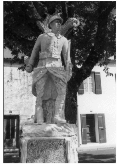
Cardell et al. (2003) carried out a study to explore the effect of salt-induced decay on buildings and stone monuments located in southwest France. Some of the historical buildings investigated by the researchers include the church of Esnandes, the church of Notre Dame in Surgeres, and the cemetery of Perigmy in La Rochelle. Some of the monuments studied include the memorial statute for the victims of the WWII in Nieul Sur-Mer (Cardell et al., 2003, p. 167).
Sampling Methods
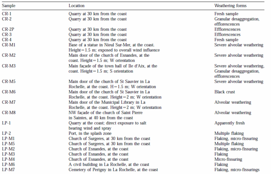
The sampling procedure was based on four criteria namely: (1) the distance between the object and the coast; (2) the nature of the calcareous stone; (3) types of weathering; and (4) height and orientation of the monuments and buildings selected for the study (table 1).
Analytical Methods
The researchers examined 21 samples to determine the characteristics of decayed stones and newly quarried stones from the sampled buildings and monuments. An agate mortar was used to convert these samples into fine powder. An X-ray diffraction was used to determine the efflorescence and the mineral composition of stones while an energy dispersive X-ray fluorescence was used to examine the bulk components of the stones. In addition, the researchers used mercury intrusion porosimetry (MIP) to analyse the petrographic attributes of the decayed and fresh stones. This is because the morphology plays an integral role with respect to the deterioration process (Cardell et al., 2003, p. 168).
Contribution of Seawater to the Salts
The researcher also examined the contribution of seawater to the salts in the sampled stones. The seawater contribution was estimated by comparing concentration ratios of calculating ions/sodium ions with those present in seawater. The following equation was used to compute the enrichment factor (EF):
Insoluble salts (X) = (X/Na) soluble salt/(X/Na) sea water
Where X= the concentration of the calculated ion; Na+= the concentration of the indicator element. In addition, an EF that is close to or equal to unity means that the main source of element X is seawater (Cardell et al., 2003, p. 168).
NaCl Crystallization Pressure
NaCl crystallization pressure was computed to assess the potential vulnerability of the selected stones to salt decay. This is because NaCl is a major component of stones. What is more, salt weathering is mainly caused by the upsurge of crystal pressure against capillary walls. Some studies have shown that large pores encourage the growth of salt crystals thereby exerting pressure against pore walls (Cardell et al., 2003, p. 169).
Results
Soluble Salts
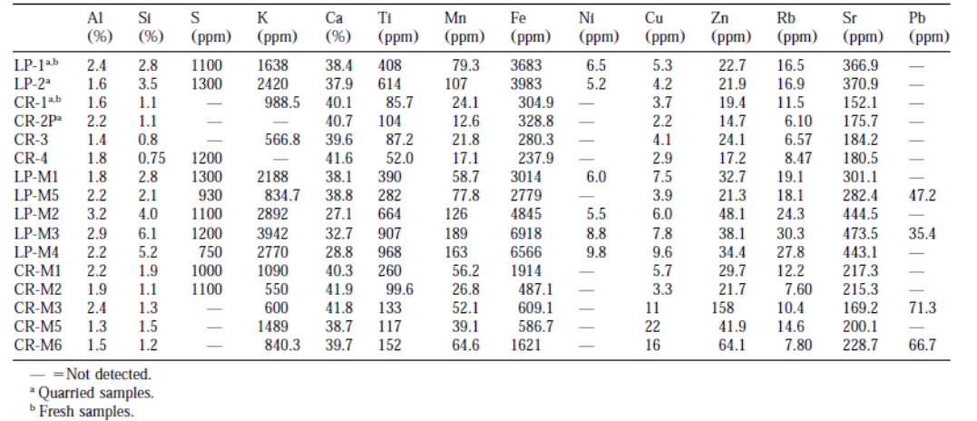
Table 2 shows that fresh stones have less soluble salts compared to decayed stones retrieved from buildings and monuments. The outcomes are presented in milliequivalent/gram so as to assess the correlation between anions and cations. Samples of decayed La Pallice stones have fewer salt contents compared to samples from decayed Crazannes. La Pallice sample has more quantities of NO3 than other samples. Samples from fresh Crazannes had more quantities of chloride ions (CR-1 and CR-4) compared to samples from La Pallice stones. Samples from monuments had higher quantities of nitrate ions than was projected. The samples from decayed Crazannes in the quarry had the highest quantities of sodium ions implying the presence of sodium salts. Conversely, the samples from buildings and monuments had higher quantities of chloride ions than sodium ions (Cardell et al., 2003, p. 171).
Enrichment Factors (EFs)
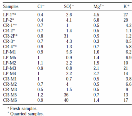
Table 3 shows the outcomes of enrichment factors (EFs) of soluble salts found in the samples. An enrichment factor that is close to unity (1) means that the chloride ions in the samples originate from the marine environment. Therefore, the EFs of 4o (for CR-M6) and 36 (for CR-M5) imply atmospheric effluence as a potential source. The magnesium ions (Mg2+) found in the Crazannes samples originated from the seawater. On the other hand, the high enrichment factors for magnesium ions in the samples from La Pallice stones imply sources other than marine (Cardell et al., 2003, p. 172).
Crystallization Pressure
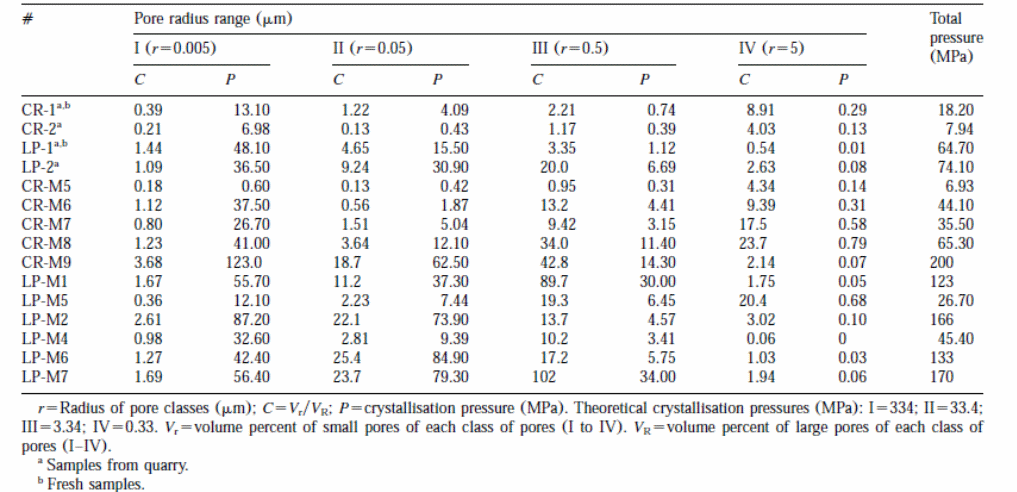
Table 4 shows the computed values of crystallization pressure of the sample stones. High crystallization pressures were attained. The highest crystallization pressures were detected in samples obtained from Crazannes and La Pallice micrite. The researchers found that the crystallization pressure detected in the samples was higher than the tensile strengths (Cardell et al., 2003, p. 173).
Optical Microscopy
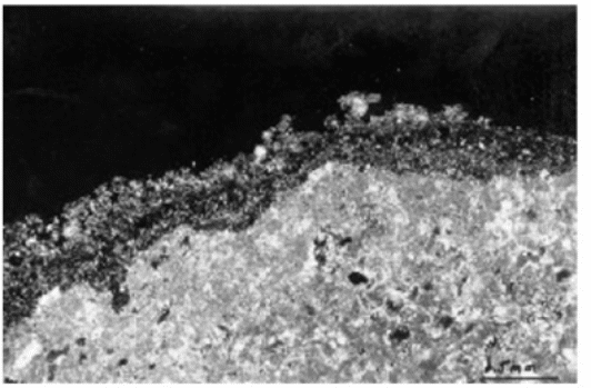
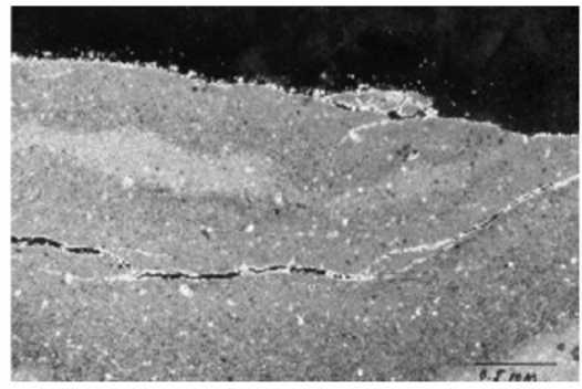
The researchers found that samples from decayed and fresh stones have identical mineralogy and texture. Crazannes (CR) had intragranular porosity (moldic pores) and intergranular porosity (large pores). Carbonate cement dissolution was found to be active among the decayed stone samples with pores estimated to be 0.8mm (Fig. 12). The salts found in the filling pores reduce the porosity near the surface of the stone samples. Figure 12 gives you an idea about the components of black crusts. They include halite, quartz and carbonaceous materials found in clay and gypsum. The researcher also observed Salt crystallization and granular disintegration at around 1 cm beneath the crust surface. Samples of the decayed stones have a network of fissures that run parallel to the surface and restricted to the initial 5 mm from the crust surface. The appearance of micro-fissures in the uppermost section of the stone (fig. 13) produces scales that run parallel to the bare surface (Cardell et al., 2003, p. 170).
Field Survey of Concrete Bridges
The study examines seven concrete bridges located around Goteborg. In this subsection a brief description of the study and findings are provided.
Determining Response
Materials were taken from the sampled bridges for further examination in the laboratory. The intention was to determine the response from the concrete used in those bridges. The analysis focused on chloride penetration, concrete cover, and visible signs of reinforcement corrosion. Chloride penetration is presented as chloride penetration profile where the ratio between chloride and calcium at different depth level are highlighted. Therefore, the chloride penetration profile shows the amount of chloride and calcium at different intervals with increasing depth. The powder samples obtained from the selected bridges are dissolved in acid and soda and analysed through potentitonmetric titration.
The concrete cover is determined using an electric cover meter. It should be noted that the electric cover meter only provides an estimated value of the depth covered. Accurate results can only be obtained when the real time measurements are taken during the drilling process. The visible signs of reinforcement corrosion entail real time observation of cracks, rusts stains or cracks with precipitation of corrosion.
Using the information obtained from the potentitonmetric titration it is possible to establish the chloride threshold value for the reinforced concrete. Besides the above three tests, CTH test was carried out to determine chloride diffusivity. Another investigation included the moisture conditions and frost resistance. The cores used to establish chloride diffusivity, moisture content, and frost resistant were 100 millimetres in diameter, whereas those used in establishing chlorine penetration were 50 millimetres in diameter.
Surveyed Bridges
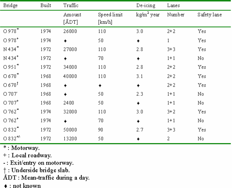
As mentioned earlier the survey covered seven bridges around Gotenborg in Sweden. The sampled bridges represent “typical Swedish concrete road bridges “which are over two decades old. In this case typical Swedish road bridges refer to the bridges that are designed and built in accordance to the Swedish standard. The Swedish standard for concrete road bridges requires K 400 concrete, 300-360 kg/m3 cement content and wc of 0.45 to 0.50. All the selected bridges are motorway bridges with relatively heavy traffic.
The seven selected concrete road bridges include Bridge N 434, Bridge O 670, Bridge O 762, Bridge O 832, Bridge O 951, Bridge O 951, and Bridge O 978. Bridge N 434 was built in 1972 over highway E6. The bridge is located approximately 30 kilometres south of Goteborg, where highway E6 crosses the motorway between Osala and Kungbacka. The study examined the southern side beam of the bridge slab and the southern columns which are located in the middle and side of the bridge. Bridge O 670 was built in 1968 and is located 20 kilometres north of Gotenborg, where highway E6 crosses Nordre Alv in Kungalv. The study was carried in the western side-beam and the underneath slab beam.
Bridge O 707 was also built in 1968 and is located a few kilometres from Gotenborg at the exit and entry road to highway E6. The study was conducted on the eastern side beam and the column on the local road. Bridge 0 762 was constructed in 1974 where highway Rv40 crosses Landvettervagen at Slam by. The road is situated13 kilometres from Gotenborg. The study was carried out on the northern side-beam and the south east column. This bridge is located 2 kilometres west of bridge 0 978. Bridge 0 832 was constructed in 1972 and is situated 7 kilometres east of Gotenborg. The bridge is found at the exit and entry to the highway E20. The Study was conducted on the northern side beam and north east column.
Bridge 0951 was also put up in 1972 and is located 20 kilometres south of Gotenborg. The bridge is found where the local road crosses highway E6 at Lindome. The examination was carried out in the southern middle column. Lastly, Bridge 0 978 was built in 1974 and is located 15 kilometres east of Gotenborg. The bridge is situated where a local road crosses highway Rv40 at Landvetter. The examination was conducted on the western side-beam and the middle-columns. This bridge is located about 2 kilometres off bridge 0762. The study discovered that the concrete covers of the selected bridges vary between 22.5mm (underside slab) and 45-55 mm (side beams). The undersized concrete cover of the underside slab is most likely to be as a result of inefficiency during the construction period and the absence of quality management.
Environmental conditions for different bridges
In this part the study examines the regional climate for Gotenborg and specific road climate for each concrete bridge. The regional climate of Gotenborg region is given is in figure 14 below. Table 5 shows the monthly mean values for temperature and humidity. The road climate for the selected bridges is given in figure 8.

There are many causes of deterioration of concrete structures but the most serious of them all is salt attack. Salt migrates into concrete through a number of steps. The first step is known as the latent period. In the latent phase chlorides penetrates the concrete cover at a lesser depth and are not capable of activating corrosion of the metallic reinforcement (Sergi, Yu & Page, 1992, p. 68). The second step is known as the progressive period. In this phase chlorides penetrates the reinforced concrete to greater depth and is capable of corroding the metallic reinforcements. The amount of chloride at this level exceeds the threshold (Sergi, Yu & Page, 1992, p. 68).
The third step is known as the acceleration stage where cracks and rusts can be observed. The cracks expose the metallic reinforcements to the environmental conditions thus increases the rate of corrosion (Sergi, Yu & Page, 1992, p. 68). The last stage is known as the deterioration phase where corrosion of metallic reinforcements goes on and the entire concrete structure starts losing some of its cross sectional area. At this stage the concrete structure begins to weaken and can go down any time (Sergi, Yu & Page, 1992, p. 70). The structure is no longer capable of providing its intended service and should either be repaired or brought down under extreme cases (Kawano, Watanabe & Koga, 2001, p. 96).
The cost of maintaining and repairing deteriorated concrete structures is normally high. Government usually spent billions of dollars to maintain and repair deteriorated infrastructures such as roads, bridges, and buildings among others. Cost incurred under such circumstance normally includes inspection cost, surface coating, concrete repairs, cathodic protection and reinforcing structures using external cables and piers. The cost of maintaining concrete structures that have been deteriorated by salt attacks can also go up as a result of corrective measures. When defects are observed in these structures it means that salts has penetrated to greater depth and the content has surpassed the threshold value.
The most common method of repairing concrete structures especially roads and bridges that have been subjected to salt attacks are surface coating and cut off repair. However, the two methods do not guarantee discontinuation of further deterioration. According to Haynes et al. (2010, p. 260), there are two most cost-effective approaches to maintaining concrete structures. The first approach is developing preventive maintenance schemes and the other one is developing effective repair methods (Haynes et al., 2010, p. 260).
Some of the repair methods considered to be effective include electro-chemical rehabilitation, for instance, cathodic protection and desalination (Lindvall, 2001, p. 326). To achieve this it is important to enhance structural diagnostic techniques which are not destructive since it is very difficult to tell the level of deterioration by mere observation (Lindvall, 2001, p. 327). Examples of diagnostic procedures include the rebound number and establishing the level of salt penetration. The rebound numbers determine the strength of the concrete. The depth of salt penetration determines the quality of the concrete and the level of destruction. Half cell measurements are normally conducted to determine the degree of corrosion (Lindvall, 2001, p. 328).
According to Kawano, Watanabe and Koga (2001, p. 98) even non destructive diagnostic tests do not necessarily give accurate results. For instance, half cell potential measurement is not 100 percent reliable for estimating the level of corrosion in concrete components. Half cell potential measurement taken on the concrete surface is likely to be influenced by the humidity level on the concrete cover. In addition, half cell potential measurement of real concrete structure can give misleading results because of the polarization of the macro cells. Therefore, the most effective diagnosis for measuring the level of corrosion among the metallic components of reinforced concrete is ASTM C876 (Watanabe & Koga, 2001, p. 98).
ASTM C876 diagnostic method averts up to 95 percent of the errors made by half cell potential measurement (Watanabe & Koga, 2001, p. 98). The new diagnostic method also gives information of corrosion risk and corrosion rate. Half cell potential measurement only provides information on corrosion risks. Information on corrosion rate helps in determining the service life of a given concrete structure (Lindvall, 2001, p. 328). The rate of corrosion can also be determined by measuring polarization resistance. Polarization resistance can also be measured using AC impedance method. However, this method is not without shortcomings. Among its problems are selection of frequency and conversion of polarization resistance to corrosion current. To improve the measurement of corrosion risk and frequency, researchers have come up with a new method known as LPR. Although this method is still under study, it is believed to be the most efficient and reliable (Watanabe & Koga, 2001, p. 98).
Findings
The study analysed all the chloride penetration profiles from the cores taken prior to and after the commencement of the season when deicing salts are applied in the road. When the deicing salts are applied on the road chlorides infiltrates the concrete. However, during the summer chlorides on concrete surface are swept away. The study established that the chloride penetration rate is higher for perpendicular surfaces during the summer. On the other hand, the total amount of chloride penetration is highest for horizontal surface during the winter.
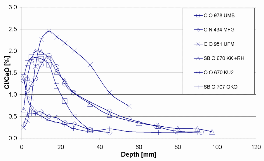
Figure 15 below shows a selection of chloride penetration profile from the sampled bridges. From the first part of the indices, C denotes a profile from a column, SB from a side beam and from other parts of the structure. The second part indicates the bridge from which the profile comes from and the last part (part three) point out the name of the profile. The exposure time for the selected bridges ranges from 25 to 30 years.
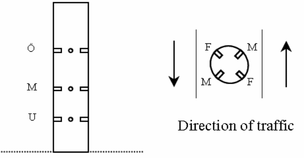
Chloride penetration in the bridges 0 951, 0 978 and N 434 columns were examined on three different elevations over the highway and four diverse orientations towards the traffic. Figure 16 below presents different sampling spots while figure 19 presents penetration profiles from the column of Bridge 0978. The index U, M and O indicate the height over the highway whereas shows the direction towards the traffic. In figure 17, the first letter in the index box denotes the height over the highway and the subsequent letters represents the orientation towards the traffic the cores were drawn.
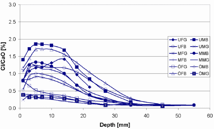
According to the findings of the study chloride penetration in Bridge N 434, Bridge 0 762, Bridge 0 832, Bridge 0951 and Bridge 0 978 were still at the latent stage. The chloride penetration on this bridge has not surpassed the threshold level and this means that they still can not activate corrosion in the metal reinforcements. Chlorides have penetrated the concrete cover to a lesser depth. However, chloride penetration in Bridge O 707 and Bridge O 670 is at the progressive stage. This means that the chlorides have penetrated the concrete to a greater depth and is capable of corroding the metallic reinforcements. The amount of chloride at this level exceeds the threshold. Luckily, none of the seven bridges have reached the acceleration and deterioration stage. These are the two most dangerous phases. Cracks and rusts can be observed in the last two phases. The cracks expose the metallic reinforcements to the environmental conditions thus increases the rate of corrosion. The deterioration phase where corrosion of metallic reinforcement continues and the entire concrete structure starts losing some of its cross sectional area. At this stage the concrete structure begins to weaken and can go down anytime. The structure is no longer capable of providing its intended service.
One of the possible reasons why the first group is still in the latent stage is ages since they are not as old as the last two. In spite of the fact that the concrete covers of the selected bridges vary between 22.5mm (underside slab) and 45-55 mm (side beams), chloride penetration level were not as deep as expected. This may be attributed to high architectural and building standards being observed in the Swedish construction sector. In addition, the chloride penetration level is perplexing given the high amount of salts used during the winter season for deicing. The observable cracks in a number of these bridges are because of mechanical factors and not chemical factors.
Discussion
Crazannes Sparite (CR)
Previous studies have shown that the chemical and physical weathering mechanisms that facilitate the development of the alveoli are correlated with environmental and topographical conditions, and lithology of the rocks (Turkington 1998; Rodriguez-Navarro & Dohene 1999). The outcomes from SEM reveal that weathering in Crazannes is caused by the physical and chemical mechanisms (i.e. Salt crystallization and cement dissolution) that result in granular disintegration and eventually alveolar weathering. A comparison of the petrographic attributes of decayed and fresh stones reveals that cement dissolution is caused by sea-salt spray. This is because the researchers did not observe any dissolution in the fresh stones in the quarry (Cardell et al., 2003, p. 175).
The dissolution of carbon cement results in a well-linked porous network that augments total porosity. As a result, the saline solution flows deeper into the interior of the stone. Thus, the amount of saline solution that flows inward in fresh stones is less than in the Crazannes sport. The rate of evaporation is directly related to the total porosity. Thus, an increase in total porosity augments the inward flow of saline solutions via capillary action. The SEM observation reveals a higher presence of salts in the interior parts of the Crazannes sparite compared to La Pallice micrite. This finding is in concurrence with the findings by Cardell et al (2002) who measured the depth, salt content and porosity of calcareous stones (Cardell et al., 2003, p. 175).
The enrichment factors results for a majority of salts found in Crazannes stones originate from seawater. The elevated enrichment factor for potassium ions (K+) in stone samples obtained from St. Sauvier church is attributed to bird droppings. What is more, stone weathering denotes alteration of the porous media particularly with respect to the distribution of pore size and total porosity (TP). The increase in total porosity in CR-5 and CR-2 samples may be due to the salt crystallization pressure and cement dissolution. On the other hand, the reduction in total porosity in CR-M6 sample is caused by the entrapment particles, salts and minerals. What is more, several studies have used mechanical and structural parameters to document the vulnerability of the stone to salt crystallization pressure (Turkington 1998).
Stone breakages occur when the crystallization pressure (within the pore network) surpasses the stone’s tensile strength. The Crazannes stone had higher crystallization pressures (between 35.5 MPa and 200 MPa) compared to the tensile strength (0.9 MPa). In other words, salt crystallization is the major mechanism that causes weathering in Crazannes stone. Consequently, other salt damage mechanisms (i.e. Chemical weathering and hydration pressure) are believed to have negligible impact to the current damage seen in the sample stones (Cardell et al., 2003, p. 175).
La Pallice Micrite
The amounts of Mn, Ti, K, Si and Rb found in La Pallice micrite are attributed to the existence of Fe-Oxi-hydroxides and phyllosilicates in this stone sample. The results of EFs reveal prominent K+ values in the entire La Pallice samples which imply that bird droppings are the most likely source sources for samples obtained in La Rochelle. In addition, the presence of phyllosilicates in these samples partly explains the high EFs for Mg2+. What is more, the results of the optical microscopy imply that the secluded micro-cracks that emerge near the surface of the stone causes La Pallice to start weathering. As weathering continues and fissures band together, an interlinked fissure network emerges and infiltrates deeper causing the stone material to disintegrate. The electronic and optical microscopy shows the crystallization of salts on the surface of the stone. This happens because thick crystalline texture prevents the movement of vapor and water inside the stone. In addition, it partly explains the low levels of evaporation in La Pallice micrite as demonstrated by the whisker-like crystals seen via SEM. It seems that the crystalline morphology developed at low supersaturation ratios. The results of this study confirm that La Pallice stone can preserve moisture for a longer period after a rainfall (Cardell et al., 2003, p. 175).
The Role of Salt Spray in the Weathering Mechanism
While some damage may surface in stones adjacent to the ground level, most of the stone weathering takes place on the higher sections of the buildings and monuments where groundwater cannot reach the stones. Thus, when water enters these stones in the gaseous form, the process of salt crystallization is related to sea-spray deposition. However, the findings by Cardell et al. (2003) show that a salt weathering test (performed under controlled environment) can be used to replicate the salt weathering that occurs in coastal regions. A study by Snethlage and Wendler (1997) reveals that the maximum amount of moisture emanating from wet/dry cycling occurs at the surface of thick stones (i.e. LA Pallice micrite) compared to broader and deeper penetration in coarse porous stones such as Crazannes sparite (Cardell et al., 2003, p. 176).
Some previous studies have shown that stones with high concentration of small pore are more vulnerable to salt attack compared to those with macropores (Rossi-Manaresi & Tucci 1991). However, the findings by Cardell et al. (2003) reveal that inconsistencies restrict the degree to which this sweeping statement can be made because Crazannes sparite is susceptible to higher weathering compared to La Pallice micrite. This finding concurs with the results of Cardell et al (2002) who demonstrated a positive correlation between the level of porosity and weathering.
What is more, Cardell et al. (2003) reports that salt crystallization results in physical stress in the pores that eventually leads to the disintegration of both the La Pallice micrite and the Crazannes Sparite. For instance, alveolar weathering in Crazannes sparite occurs via granular dissolution and the physical action of salt crystallization. On the other hand, salt crystallization causes the development of a flaking pattern in La Pallice micrite with uniform and knit crystalline texture. Weathering begins by generating remote microfissures that run parallel to the surface. A manifold fissure network develops when cracks enlarge and move deeper into the stone.
Chloride Penetration in Bridges
The chloride penetration in bridges 0 951 and N 434 were found to follow the regular pattern, with high penetration at lower level than higher levels. However, the study found high chloride penetration on the bridge 0978 on the surface directed towards the traffic. In the same bridge the surface oriented from the traffic was found to have low chloride penetration. One of the possible explanations for this is that airborne chloride such as the chlorides contaminated by aerosols always tend to follow wind direction and are deposited on the leeward side (surface directed toward the traffic). Most of these chlorides are not washed away, therefore each time more chlorides are deposited in these surfaces chloride concentration increases. However, the chloride deposited on the surface facing the windward side (away from the traffic) are frequently washed away by the wind in all heights, which leads to low penetration.
Deicing of Swedish highways is normally carried out during the early morning hours or during the night. Therefore, the road surfaces exposed to morning splash are the one with the highest chloride concentration. This is evident on Bridge 0 951 where the surface directed towards the traffic coming from Gotenborg has high chloride penetration depths in comparison with other surfaces. Traffic intensity under this bridge is high towards Gotenborg in the early morning and from Goteborg in the evening.
Constructing Durable Buildings in Saline Environment
There are several factors that must be taken into account in order to construct a durable building in saline environments. For instance, the strength of any building or concrete structure depends on the design and concrete components.
Concrete Resistant to Saline Conditions
Permeability is an integral aspect with respect to construction in saline environments. A highly permeable concrete is extremely vulnerable to saline damage. The susceptibility of concrete to salt attack depends on a number of factors which includes the size of the pore and their distribution in the concrete. The durability of concrete can be enhanced in the following ways:
- Decreasing the ratio of the cement and water
- Ensuring that the concrete is properly compacted
- Using suitable curing methods and duration
- Selecting suitable concrete components (I. e. aggregate, sands and cement type) that correspond to the conditions of the site
- Reducing the pounding of water on the surface of concrete
- Procuring construction materials from a certified supplier
It is also important to mention that permeability can be reduced by increasing the tensile strength of the concrete. Nonetheless, there are other design standards that must be adopted to ensure concrete buildings remain durable in saline environment (McGhie 2003).
Preventing Water and Salt Moving into the Building
Many buildings in New South Wales (NSW) have a damp-proof course (consisting of sand layers) inserted beneath the concrete slab (fig. 18). The damp-proof course has several benefits. For example, the damp-proof course (DPC) stops hard materials from puncturing the membrane in the underlying soil. In addition, it curbs soil moisture from rising via capillary action. Therefore, a building will less susceptible to saline damage if the layers of damp-proof course are increased (McGhie 2003).
Preserving Good Drainage on a Building Site
It is important to evaluate water movements at different scales with regard to salt mobilization. For example, water may penetrate a groundwater system and collect salt from soils and rocks along the way before it perforates into the building. Thus, one way of solving this problem is by carrying out on-site repair at the point where the water enters groundwater. What is more, there are a number of socioeconomic decisions for example how much indigenous vegetation to keep, whether to supply piped potable water, penetrate rainwater, and use septic containers that affect the movement of water and salts. Thus, a long term plan is required in order to monitor, assess and manage the potential adverse effects of salinity on buildings (McGhie 2003).
Conclusion and Recommendations
Conclusion
This thesis provides a greater understanding regarding the consequences of constructing buildings in saline environments. The study focuses on different factors that cause deterioration of concrete buildings and monuments in western France. It has also made deductions regarding the corrosion mechanisms that cause saline damages on the identified buildings and monuments. It has been established that salt weathering and the marine environment are the main causes of decay in the stones obtained from monuments and buildings. This thesis has demonstrated that various deterioration mechanisms work synergistically on different types of stones resulting in dissimilar weathering forms. For instance, it was observed that Crazannes sparite is highly susceptible to alveolar and sanding weathering. On the other hand, La Pallice micrite deteriorate due to flaking and fissuring weathering.
Concrete structures are usually subjected to unfavourable environments that reduce their durability. For example, chloride penetration is one of the main types of environmental attack that damages buildings, monuments and reinforced concrete bridges. Chloride ingress corrodes reinforced concrete structures thereby reducing their durability. Chloride attacks can either prompt early repairs or premature demolition of buildings and structures. Thus, it is important to use impenetrable concrete in order to prevent chloride ions from penetrating the building and causing damages. However, chloride ions take time to penetrate and cannot be detected easily. Thus, it is important to adopt a test measure that speeds up the process and permit the establishment of diffusion values in a short time.
Salinity refers to existence of salt in a given surrounding. Salt originates from rocks (from the weathering process), seas/oceans, or from dusts transported by wind. The most common salts are chlorides, sulphates, and nitrates. Salts are both useful and detrimental to humans and properties. Other sources of nitrate salts include nitrogen fertilizer, animal waste, industrial and urban waste, and plant remains. Salts generally attack buildings in solution forms. Salt attack is usually facilitated by both internal and external sources of water/moisture. Salts can only cause considerable damage when the concentration level is very high. The level of salt concentration is generally facilitated by a series of cycles commonly known as the salt cycle. The rate of recurrence of the salt cycle depends on the amount of water available, the speed at which the solution gets in the zone of evaporation, and the evaporation rate. Therefore, the cycle may be continuous or irregular depending on the availability of water/ moisture. The three main ways through which water/moisture moves around buildings and other structures are rising damp, horizontal damps/penetrating damp, and falling damp. Salts normally cause physical and chemical damage to buildings. The degree of damage from salt attack is dependent on the concrete structure, salt concentration and salt type. In order for these conditions to be met moisture has to be present and the rate of evaporation has to be high.
The most efficient measures of breaking the salt cycle are the prevention of water/moisture from entering the buildings or structures. The most common measures of preventing water or moistures form getting into the buildings or structures include: putting a layer of sand beneath the slab to enhance drainage and reduce capillary action; placing a waterproof covering between the sand layer and the slab; use of class bricks beneath the waterproof membrane; placing the waterproof course beneath the concrete or brick work; and putting in place and maintaining a sound drainage system.
The physical stress (in a pore) that emanates from salt crystallization was identified as the main deterioration process that results in weathering. For example, alveolar weathering in Crazannes sparite occurs via the physical action of granular degeneration and salt crystallization. Granular degeneration occurs when the carbon cement in the stone dissolves. The wind commotion (caused by marine breeze) augments uneven disintegration in Crazannes sparite. On the other hand, salt crystallization causes the development of a flaking pattern in La Pallice micrite. The weathering process begins when small fissures appear on the surface of the stone. A network of multiple fissures appears when the microfissures enlarge and pierce deeper into the stone. However, holding other factors constant, the different forms of weathering is mainly caused by the configurations of these stones.
The chloride penetration into the concrete depends on the exposure conditions and the property of the concrete. The exposure conditions in this case are the chloride and moisture conditions. The chloride penetration profile provides a very good assessment of the level of exposure in sampled bridges. Surfaces with the highest chloride penetration are more exposed than those with lower levels of penetration. The study established that exposure environment greatly influences the level of chloride penetration in the concrete structures. Other studies have even found varied chloride penetration in a single concrete structure. This means that the environmental conditions on the concrete surface must be considered to obtain accurate results during the analysis.
Salinity is a major problem that afflicts most buildings found in urban areas. The urban salinity is largely attributed to the rising subterranean water which brings salts to the surface. This problem is common in areas prone to salinity such as coastal strips, plains, and valleys among others urban development areas that can also cause localized salinity. Salinity is attributed to clearance of native vegetation, overwatering of the parks and gardens, leaking of pipes, seepage of silage pits, and blockage/alteration of the natural drainage system. Water from these sources has the capability of consolidating salt on the building sites. Therefore, the effect of salinity in the urban areas is not restricted to the zones of rising water tables.
Urban salinity is an intricate subject which involves mobilization, redistribution and concentration of salts in an urban environment and their resultant effect. Urban salinity has degraded urban infrastructure to an extent that governments are forced to spend massively on repair work and untimely replacement (Sergi, Yu & Page, 1992, p. 63). Similarly, houses and other buildings have been and continue to be degraded by the harmful impact of salinity. The impact of the urban salinity on these buildings is normally significant and takes place in a relatively short period of time (O’Caoimh, 2007, p. 12).
The study findings show that the survey of the seven bridges should have been done independently especially in the analysis of chlorine penetration. This is because chloride penetration is influenced by the surrounding environmental conditions, execution during construction, ratio of concrete components and the surface treatment, for example, curing process. Therefore, before the analysis of chloride penetration and moisture content assessment of the concrete properties and the impact of probable surface treatment have to be carried out. One of the major problems encountered during the study is quantifying environmental actions. The statistical quantification of environmental action using mathematical models proved to be a very difficult task during the study. It is not easy to find structures with similar concrete composition exposed to environmental conditions. This makes it very difficult to measure differences between dissimilar environmental conditions. Therefore, this kind of study requires excellent data of concrete structures with similar concrete composition exposed to similar environmental conditions.
This thesis has shown that irregularity restricts the validity of the observations made above. This is because salt weathering is the ultimately responsible for the disintegration detected in both stone types. This means that both delicately porous stone and roughly porous stone are extremely vulnerable to salt attack under the right conditions.
Recommendations
There is no doubt that salt attacks can have disastrous effects on buildings found in saline environments. Therefore, a conversation strategy must be developed to guide the construction and maintenance of buildings in saline environments. For example, the strategy must include appropriate salt extraction mechanisms as well as the suitable protection and consolidation interventions with respect to the stone types. What is more, appropriate studies must be undertaken to ascertain the physical, chemical and mechanical properties of the stones used for construction purposes in saline environments. For instance these studies should lend credence on the characteristics of the pore systems since they regulate the chemical and physical processes.
The Australian government has a building code that governs constructions in saline environments. For example, AS 3798 regulates construction of commercial and residential buildings in saline conditions. For instance, it stipulates that site investigation must entail the identification of swampy areas. It states further that inappropriate component for fill comprises of soluble materials such as salt. Field studies must be conducted to determine whether to increase or reduce the amount of moisture in the fill with salt water (McGhie 2003).
Future Prospects
The research carried out and reported within this thesis is involved with determining the effects of constructing buildings in saline environments as well as the possible solutions. As explained with the literature review in chapter two, salt attack is manifested in different ways. However, this thesis investigated two case studies to determine the effects of salinity on road bridges, monuments and buildings. Future research should explore how the chloride penetration differs in diverse marine conditions. For instance, samples from the same concrete should be studied in different marine conditions. What is more, future research should explore the relationship between chloride ion penetration in bridges and buildings with the environmental actions. For instance, a mortar disk can be utilized to explore the effects of environmental actions on the surface of a bridge. The researchers should use these disks to extract a uniform and precise material.
Further studies should also be done to explore the relationship between poor concrete preparation (during construction) and durability. This can be done by investigating the effect of chloride attack on two adjacent bridges, constructed using steel and board reinforcements. The profiles of chloride attack on each bridge should then be examined. Finally, further research should be done to investigate the relationship between surface curing and concrete durability. This study can be done by comparing the results of chloride penetration in both the treated and untreated concrete.
References
Beeby, AW 1978, ‘Cracking and Corrosion: Concrete In the Oceans’, Technical Report No. 1, Cement and Concrete Association, Slough, United Kingdom.
Cardell, C, Delalieux, F, Roumpopoulos, K, Moropoulou, A, Auger, F & Van Grieken, R 2003, ‘Salt-induced decay in calcareous stone monuments and buildings in a marine environment in SW France’, Construction and Building Materials, vol. 17, pp. 165-179.
Cardell-Fernandez, C Yebra, A & Van Grieken R 2002, ‘Combined digital image processing SEM-EDX and BSE data acquisition to determine porosity and salt distribution in-depth in porous materials: A methodology to quantify salt weathering’, Mikro-chemical Acta, vol. 140, pp. 9-14.
Hansson, C & Sorenson, B 1990, ‘The Threshold Concentration of Chloride in Concrete for the Initiation of Corrosion’, Corrosion Rates of Steel in Concrete, vol. 99, pp. 3-16.
Haynes, H, O’Neill, R, Neff, M, & Mehta, PK.2010, ‘Salt Weathering of Concrete by Sodium Carbonate and Sodium Chloride’, ACI Materials Journal, vol. 107, no. 3, pp. 258-266.
Irassar, EF, Di Maio, A & Batic, OR 1996, ‘Sulphate Attack on Concrete with Mineral Admixtures’, Cement and Concrete Research, vol. 26 no. 1. Pp. 113-123.
Kawano, H, Watanabe, H & Koga, H 2001, ‘Nationwide Survey of soundness of concrete structures’, Second International Conference on Engineering Material, pp. 93-100.
Lindvall, A 2001, Environmental Actions and Response – Reinforced Concrete Structures exposed in Road and Marine Environments, Publication P-01:3, Department of Building Materials, Chalmers University of Technology, Göteborg, pp. 320-330.
Lindvall, A 2002, Environmental Actions and Response: Reinforced Concrete Structures Exposed in Road and Marine Environment, Chalmers University of Technology, Goteborg.
Mehta, PK.1991, Concrete in the Marine Environment, Elsevier applied science, London.
Melchers, RE, Li, CQ, & Lawanwisut, W 2008, ‘Probabilistic modelling of structural deterioration of reinforced concrete beams under saline environment corrosion’, Journal of Structural Safety, vol.30, pp.447–460.
McGhie, S 2003, Building in a Saline Environment, Department of Infrastructure, Planning and Natural Resources, Sydney.
Midgley, H & Illston, J 1984, ‘The Penetration of Chlorides into Hardened Cement Pastes’, Cement and Concrete Research, vol. 14, no. 4, pp. 546-558.
Nilsson, LO, Andersen, A, Luping, T, & Utgennant, P. 2000. Chloride ingress data from field exposure in a Swedish road environment, Chalmers University of Technology, Göteborg.
O’Caoimh, E 2007, Building in a Saline Environment- An awareness Course for NSW, NSW State Government.
Rodriguez-Navarro, C & Dohene, E 1999, ‘Salt weathering: Influence of evaporite rate, supersaturation and crystallization pattern’, Earth Surf Processes Landform, vol. 23 no. 3, pp. 191-209.
Rossi-Manaresi, R & Tucci, A 1991, ‘Pore structure and the disruptive or cementing effect of salt crystallization in various types of stone’, Stud Conserv, vol. 36, pp. 53-58.
Sathiyanarayanan, S, Panjali NK, Saravanan, S, Srinivasan, GV 2006, ‘Corrosion monitoring of steel in concrete by galvanostatic pulse technique’, Cement & Concrete Composites, Vol. 28, pp. 630–637.
Snethlage, R & Wendler, E 1997, Moisture cycles and sandstone degradation, Chichester, Elsevier.
Stanish, KD, Hooton, RD & Thomas, MD 1996, Testing the Chloride Penetration Resistance of Concrete: A Literature Review, University of Toronto, Canada.
Stuart, M 2012, Concrete deterioration, Web.
Turkington, AV 1998, ‘Cavernous weathering in sandstone: Lessons to be learned from natural exposure’, Q J Eng Geol, vol. 31, pp. 375-383.
Watanabe, H & Koga, H 2002, General information on deterioration of existing concrete structures and recent research topics on the maintenance techniques in PWRI, Public Works Research Institute, Tokyo, Japan.