Abstract
High temperatures experienced in the Gulf Cooperation Council (GCC) countries during summer makes consumption of water straight from the taps impossible. Many homes use multiple water coolers and refrigerators 24 hours a day to cool the water. The amount of power consumed this way leads to a large additional electric load on the grid. Because of the PLC Controlled Water Cooling System design, it is possible to cool all the water used in a home centrally in the main storage tank thereby eliminating multiple cooling systems. Through a control panel that can be installed anywhere in the home, users set the desired water temperature. The panel controls a compressor, which cools water to the desired temperature. The compressor goes offline once the temperature falls to the desired level.
Introduction
TEMPERATURES in Gulf Countries rise up to 500C during summer. This makes consumption of water from tanks and reservoirs by residents extremely difficult if not impossible at all. The need for palatable water necessitates use of water coolers. Typically, a single home has several of water cooling units in addition to refrigerators used for cooling and storing cold water. With the application of a PLC Controlled Water Cooling design as proposed in this paper, it would be possible to eliminate the use of multiple water coolers and refrigerators used purposely for the cooling and storage of drinking water.
Previous Inventions
In 1974, Robert C. Webber designed a system for simultaneously cooling a building and warming water in a swimming pool. Webbers’ system employed a refrigerant running through conduits that connected the compressors and condensers. He used thermostatically controlled valves to regulate the action of the compressors and the condensers. When the building temperatures dropped below preset levels, the thermostatic valves made it possible for the refrigerant to bypass the buildings evaporator and to conduct the refrigerant through an auxiliary evaporator.
Industries employ several other systems for water chilling. One of methods used is the waterwall water cooling system designed by Kohring, F. C. He demonstrated that this method had an enhanced cooling efficiency among other advantages when compared to conventional cooling systems. Interstand cooling, runout table cooling, work roll cooling and descaling are hot strip mill applications that use this method. In addition, the system was useful in plate mills and bar mills.
Scope
This project’s design compares closely to Webbers design. The scope of the project is to design and build a system for cooling and heating water in tanks/reservoirs for domestic customers. In this design, an electronic control panel (SD-94M) has replaced the thermostatically controlled valves in Webbers design. The user uses the panel for input of the desired water temperature. The compressor is operated by a low cost SIEMENS PLC (LOGO module) which turns the compressor ‘ON’ or ‘OFF’ depending on prevailing and desired water temperature as set by the user. This paper reports on the design procedure employed and the results that were been obtained during the first semester. A brief outline of upcoming work in the next semester is included.
System Design and Implementation
Top Level design
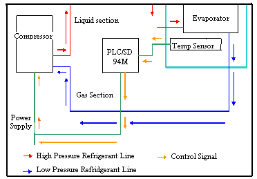
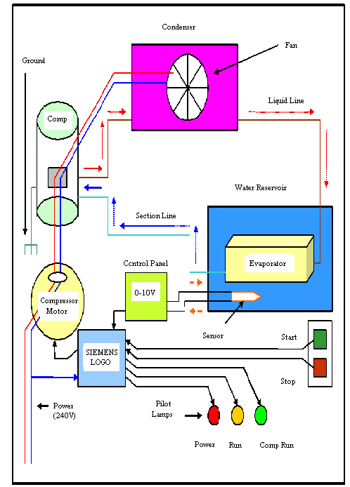
A 150-litre water tank with a temperature sensor (PT100) with an evaporator mounted inside provided water storage. The sensor provided an analogue voltage signal proportional to the system’s water temperature. An Electronic Control panel (SD 94M) as user interface, was used to provide the set point temperature. The control panel provided the signal required by the PLC, which had a 45-second delay, to operate the compressor. If the water temperature fell lower than the set point temperature, the compressor remained off but if it rose higher, then the compressor turned ON until the set point temperature was reached.

The evaporator was connected to the compressor through an expansion valve, which allowed the water to heat up each time the water cooled by more than 5°C below the set point temperature as shown in Figure 1.
Cooling System
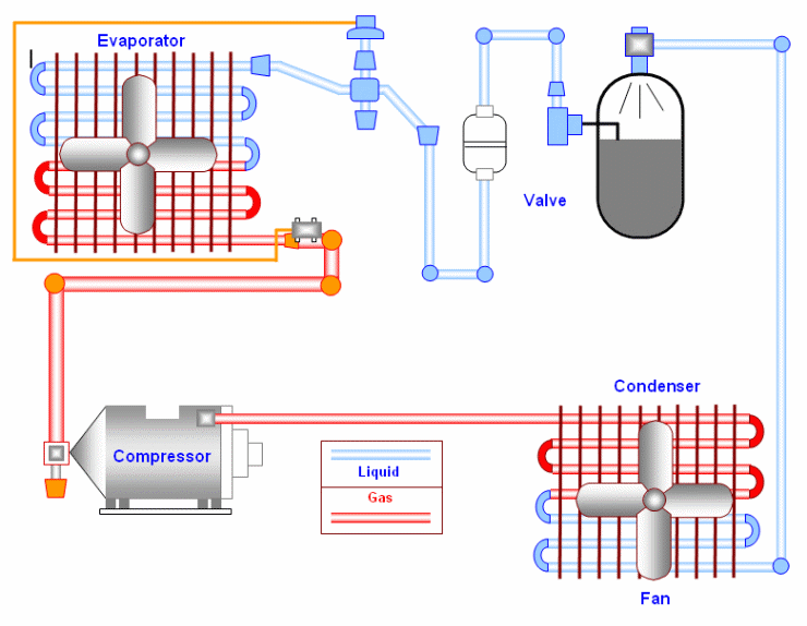
The cooling system resembled that of air conditioning systems, which employ a condensable refrigerant that interconvert’s between liquid and gaseous state depending on the attendant temperatures. This change of state makes it possible for the refrigerant to transport heat from one section to another and releases it usually through a condenser where it liquefies. The key components of a cooling system are compressor, condenser, expansion valve, and evaporator. In this design, the compressor and condenser were located outside the reservoir while the evaporator was located inside. The evaporator connects the two portions as shown in Fig 2.

System Operation
The input temperature range for the control panel is 0°C to 50°C. This input voltage is converted into a voltage level of (200mV per °C), which yields a set point voltage level of between 0V and 10V.
The sensors’ working temperature range is between -50°C to +200°C [3] in units of 1°C. Its output voltage ranges 0-10V in units of 40mV. The sensor is limited by poor resolution of the control panel’s analogue to digital converter and line noise, reducing the minimum detectable voltage to 50mV (40mV*1.25)
Since we are only concerned about temperatures between 0°C and 50°C as this is the limit of the set-point temperature we can set from the control panel, a voltage level converter in the control panel changes the sensor’s output voltage (50mV per °C) to the same level as the set-point voltage level (200mV °C). This is done by first multiplying the sensor’s voltage level by 4 to get 200mV increment per °C and then removing the -50°C to 0°C offset that is (40mV*50 = 2.5V). By doing this, the sensor’s output voltage now changes from 0V-10V with an increment of 200mV per °C that is same as the set-point voltage increment. The sensor’s voltage level (after conversion) was converted to °C by dividing by 200mV and this temperature in °C was displayed on the control panel. In this way, the user can monitor the set point and the actual water temperature on the same display.

The control panel uses a relay system to operate the compressor, turning it ON whenever the set point voltage level is lower than the sensors output and turns it off if the voltages are equal or lower than the set point voltage. The Siemens LOGO PLC provides the interlink between the relay and the compressor and, turning the compressor on each time the relay is ON and turns it OFF each time the relay is OFF.
Software Description
The software used to develop the ladder diagram was LOGO! Soft Comfort, Version 4.0.51.
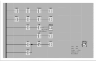
A 240V supply comes through the main power source labelled I1, indicated by the coming ON of pilot lamp Q1. The desired water temperature is then set through Input sensor I4 (Sensor PT100) which connects to the controller which regulates its functioning. The controller’s screen displays water temperature when the system turns ON. If the reading exceeds set temperature (e.g. 20c°~30c°) , Input I4 is triggered, sending a signal to delay timer T002, set at 45 seconds, as a compressor safety measure. After the delay time lapses the compressor comes on line to lower the water temperature. Upon attaining the set temperature value, Input I4 opens, stopping the compressor.
In addition to the green coloured pilot light (Q1) which indicates whether the system is on, there are also two other pilot light Q3 and Q4 which indicate whether the system is heating or cooling , respectively.

The project schedule used to conduct this project is indicated below.
Testing Results & Conclusion
The prototype was assembled on a wooden frame, which carried the 150-litre tank used, compressor, control panel, and PLC. The evaporator and the sensor were mounted inside the reservoir tank included the. All tests were undertaken at RMIT labs. The key test for the cooling system involved adjusting the set point temperature between 5°C and 20°C, which successfully caused the compressor to turn ON whenever the actual temperature was higher than the set point temperature, and OFF otherwise. These measurements were however not tested against any other temperature sensor.
Future Work
The design of the PLC Controlled water Cooling System features a closed loop structure. It does not operate in real time however because the PLC timer has a 45 second safety delay to curb sudden switching. There are plans to fit a PID controller on the same assembly in the coming semester. This will necessitate a new pole assignment design to accommodate the controller’s parameter requirements. With the PID controller online, it will be possible to activate the heating functionality with a set point of 25°C. The systems’ sensor will require calibration against different temperature sensors available in the market to enable in-depth system performance analysis. The addition of a hysteresis level to restrict the compressor to turning ON only under minor temperature changes will improve performance. Finally, the study of power consumption of the system earmarked for the next stage. This will be one of the areas for exploration in the coming semester, comparing the systems power consumption with and without a PID controller. This analysis will also include a comparison of power consumption between this system and other systems in the market.
References
Webber R.C., Building Cooling and Pool heating system, (1975).
Kohring, F.C., Waterfall Water-Cooling Systems, Iron Steel Eng. Volume 62 (1985).
LOGO! User Manual, Siemens Manual, Edition 06/2003.
Petruzella F.D., Programmable Logic Controllers, Mc-Graw-Hill.