Abstract
Robots are becoming more common in industrial settings because their capabilities outweigh human ones. They are accurate, reliable, and able to handle heavy loads, making them reduce the work expected of individuals within a given work setting. They also increase production in areas that perform repetitive jobs, thus increasing the output of a manufacturing company. Programs are used to make robots behave similarly to the human arm. The current project aims to design and develop a robotic arm that draws 3D objects from data input or sensors. The machine is programmed using MATLAB, Arduino IDE, and the DoBot interfaces with the computer through Arduino Mega Board.
Introduction
Three-dimensional printing involves manufacturing materials using additive technology, which helps build given materials by continuously adding one layer to another to form various parts of the whole. It is directly opposite to the type of manufacturing achieved by removing parts from the whole lump. Three-dimensional printing is categorized into five: extrusion, light polymerization, electron beam freeform fabrication, laminated object manufacturing1,2,3, and powder bed.
Fused deposition modeling or FDM is the most used technique in 3D printing and is the method applied in this project. It involves slicing different parts into layers, which are then translated into machine language for the printer to understand. The hot end of the printer melts the material and embeds it onto the surface onto the intended surface. The melted material solidifies, and more layers are added accordingly to produce the final part.
Robotic arms are connected segmented machines controlled by the computer, motors, and hydraulics. Such robots are primarily used in industrial applications where repetitive work requires heavy labor. Such machines can be integrated with various sensors that measure position and velocity and respond appropriately to feedback based on the input received. Other robotic arms may use cameras as their input mode and convert the signals to computer-understandable language. This project uses simple input sensors that detect shapes, distance, and degrees of freedom. The primary objective of this study is to explore robotics by making a machine that can draw a 3D design.
The current project gives critical information that helps to guide designers on ways of developing 3D printing robots. Most research in the past has focused on robots from the perspective of humanoids to enable them to replace people doing repetitive jobs. More studies have helped improve the approaches to robotic developments, making it more straightforward for subsequent developers to get critical insights that improve robotics for better performance. The areas enhanced by studies include programming and debugging methods, which have made the final machines more advanced and ready for the intended use.
The current project used some critical movement theories to help in achieving a perfect combination of the parts of the robotic arm, such that they achieved a perfect motion needed for the combined parts, such as the hand, elbow, and shoulder, with each part moving in any position direction make a perfectly solid object. The research also utilized the Arduino development board to interface the programs written and the physical parts. Arduino was considered for the project because of its ease of programming, which requires basic knowledge of C and C++. The current project uses the Arduino Mega board to translate the program that runs the board’s microcontroller.
Background of the Project
Robotic arms are inevitable in the present world where industries are using complex machines. The mechanization of factories requires machines that work synchronously to help achieve the highest possible production rate. Apart from the need to interface machines for better output, various tasks require heavy lifting, which limits humans’ possibility, hence requiring robots. Moreover, there are instances in which getting specific measures and calculations of materials may be problematic for workers, which can slow the process of resulting in faults in the final products. A 3D robotic arm is designed to determine the various measures of the object to reproduce and the specific amount of material required to make the object. It can also be fed with data and utilized the information to create something incredibly impossible by human hands within the shortest time possible.
Programs used to run robots can be changed from time to time to meet the company’s specific needs. Consequently, the functions of the arms can be changed to fit the required work or environment. For instance, it is possible to make a 3D robotic arm function as a 2D drawing robot, according to the specific needs of the programmer. For instance, a 2D robot uses only length and width to reproduce an object and draw a new one corresponding to the information fed to its terminals. A 3D arm, therefore, uses an additional orientation and depth to introduce the plane that makes the output a solid object. On the other hand, their speeds can also be adjusted to meet the specifications and production rates of the factory. Using the principles of three-dimensional symmetry, the programmer can create a robot that creates the exact material with a specified thickness in various complex parts of the object. For instance, an object with holes within the solid part can effectively be printed with the exact measurements fed into the computer, thus producing a feature-specific output fitting the industrial application.
The current project uses DoBot to produce an industrial-ready robot. The robot is mainly for training, giving learners a practical understanding of robotic arms, from code to specific designs and debugging. The robot operates using simple instructions from the provided interface, depending on the operator’s needs. Since the object uses layers, one can use it for writing and drawing 2D objects as this involves using printing of a single thin ink layer. The project uses the Arduino Mega board as its main component. It acts as the interface for the visible and invisible parts of the robot and has a special memory that stores instructions that keep the robot delivering its intended goals. The development board uses simple programming languages, including C and C++, making it one of the most straightforward approaches to producing non-industrial robots.
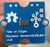
The board has input and output pins that help in connecting the computer and the robotic arm, thus facilitating the communication the user feeds to the computer and the response the arm gives in printing the object intended by the user. Thus, the Arduino Mega board used in these cases helps the user to control the DoBot. The project also utilized a secure digital (SD) card to help store the file robot should draw. The Arduino Mega board then reads the information stored in the card and translates that data into a drawing using the robotic arm. In addition, the project used the TOF sensor shown in Figure 1 below to detect the object and save the 3D version of the object on the SD card. The Arduino then translates the saved object into a sequence that DoBot understands for drawing.
Methods
The project involved several steps, including purchasing the items required, iterative design, choosing the best programming language, designing the DoBot control system, assembling and installing the heated bed, and testing all the system parts. The details of each of these steps are provided in the sections below. However, each part of the process was a little more complex than summarized in the sections.
Decision Regarding Components
The initial step involved comprehensive research regarding crucial components required to make a 3D printing robot. Each part required was determined based on the preliminary design and drawing of the parts. The components and their respective costs were determined, including the feasibility of the development.
Iterative Design
The iterative design approach was used to create and customize the components needed for the project. The idea was brainstormed, and feasibility of the project was discussed, and a perfect design was selected. The design was then created using computer-aided design (CAD) software. The components were adjusted to meet the specifications of the final project. The effectiveness of the parts was tested and adjusted appropriately or remade to match all the other components. The design processes included mounting angle, mounting system, idler system, extruder assembly, and driving mechanism.
The decision of the Programming Language
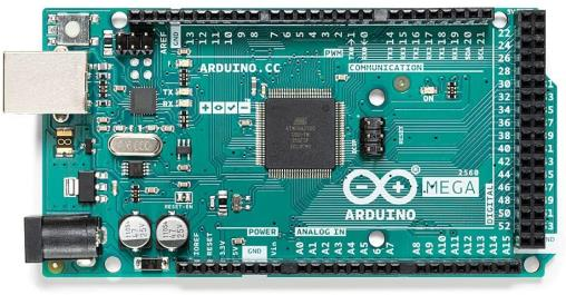
The process involved familiarizing the robot to understand how it works based on the information it receives and the outputs it produces. The process also involved analyzing the pros and cons of the different programming methods that were researched and how they could impact the cost and feasibility of the project. The simplest programming method, which is C, was then used to program the robot as it was the best technique for using the Arduino Mega board shown in Figure 2 below.
The Robot System Design
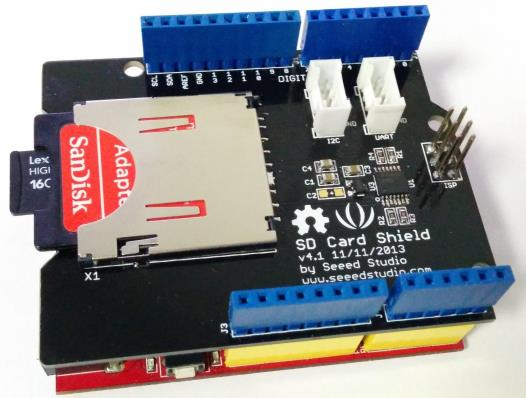
The control method for the 3D printer was determined to be the G-code, created using the slicing algorithm. However, since the robot could not execute the code, the solutions for each component were analyzed to understand a better control system fitting the project. When the prototype was completed, the entire system was reexamined to ensure that each component was suitable for its specific purpose and placement. The G-code was then translated through a series of iterations by adding new codes and testing them before adding more features. The program final program was then compiled and simulated, and saved to the SD card, which was mounted on the SD card shield shown in Figure 3 below.
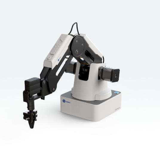
The extruder control was brainstormed to ensure easy and quick ways to control the temperature of the hot end. The coordinate frame was configured according to the manufacturer’s documentation, and a quick test was performed to ensure everything worked correctly. Finally, the robot’s control system was implemented using smaller subsystems, which ensured a lean approach to design, implementation, and tests of every component before they were combined to form the complete version of the robotic arm. The project utilized the DoBot magician shown in Figure 4 below as the arm of the robot.
Assembly and Installation of the Headed Bed
The project considered using a heated bed because of the tendency of the material used in the printing curling and the need to achieve error-free printing. The heated bed was also designed through an iteration design. All the parts were effectively fitted, and a custom-made design with the required heat distribution was achieved and embedded in the robot. The final connection was achieved by connecting the systems, as shown in Figure 5 below.
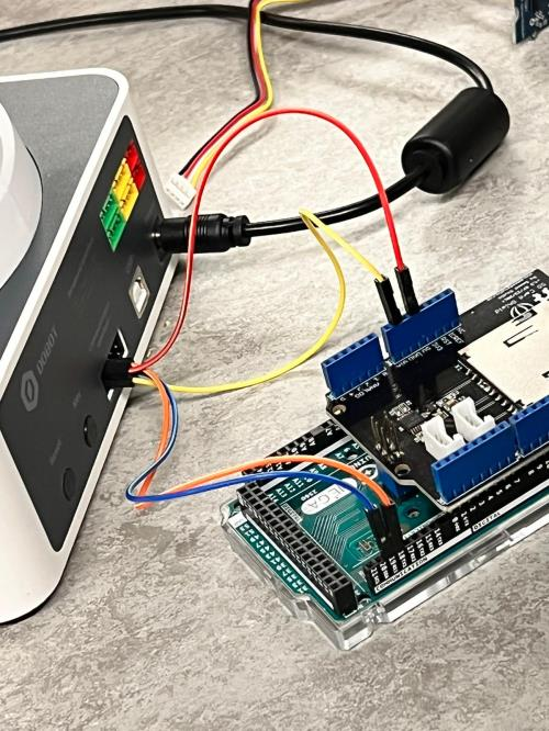
The software part of the project is also provided below. First, MATLAB was used to run and simulate the project as it provided the interface through which the 3D object was processed. The following code was used in the MATLAB software to process the object the sensor picked.
regionSize=5; %Region size
INPUT = ‘image1.jpg’; %Load image
in_img = imread(INPUT);
in_img = rgb2gray(in_img);
[sizeX,sizeY] = size(in_img); %Check if image is square
if sizeX~=sizeY
disp(‘Input image is not square.’)
disp(‘Please load a square image.’)
return
end
in_img = imresize(in_img,[280 280]); %Resize image
%Show input image
figure(1);
imshow(in_img);
title(‘Input Image’);
figure(2);
halftone_img=floydHalftone(in_img);
imshow(halftone_img);
title(‘Halftone Image’);
%Initialize path arrays
xPath=[0];
yPath=[0];
for j = 1:2*regionSize:size(in_img,2) %Process image via regions using nearest
neighbor search
for k = 1:regionSize:size(in_img,1) %Odd rows
halftone_region = floydHalftone(in_img(j:j+regionSize-1, k:k+regionSize-1));
%Convert region to halftone
[x,y]=find(halftone_region==0); %Find locations of non-zero elements
xPathRegion=ones(size(x)); %Pre-allocate local region arrays for speed
yPathRegion=ones(size(y));
idxNN=knnsearch([x y],[0 0]); % Use NN to top left corner as region path start
if isempty(idxNN) %Error case for purely white regions
xPathRegion=0;
yPathRegion=0;
else
xPathRegion(1)=x(idxNN);
yPathRegion(1)=y(idxNN);
i=2;
while size(x,1)>2
idxNN=knnsearch([x y],[xPathRegion(i-1) yPathRegion(i-1)]); %Find
index of NN
xPathRegion(i)=x(idxNN); %Add visited location to path
yPathRegion(i)=y(idxNN);
x(idxNN)=[]; %Remove visited location from array of unvisited points
y(idxNN)=[];
i=i+1;
end
end
xPathRegion=xPathRegion+j; %Offset local path for global location in image
yPathRegion=yPathRegion+k;
xPath=[xPath xPathRegion’]; %Append neighborhood path to total path
yPath=[yPath yPathRegion’];
figure(3) %Plot current total path as animation
plot(yPath,-xPath,’k’);
title(‘Pen Path’);
axis([0 size(in_img,2) -size(in_img,1) 0]);
drawnow;
end
j = j+regionSize; %Increment vertical counter
for k = size(in_img,1)-1:-regionSize:1 %Even rows
halftone_region = floydHalftone(in_img(j:j+regionSize-1, k-regionSize+2:k));
[x,y]=find(halftone_region==0);
xPathRegion=ones(size(x));
yPathRegion=ones(size(y));
idxNN=knnsearch([x y],[0 size(in_img,1)]); %Use NN to top right corner as
region path start
if isempty(idxNN)
xPathRegion=0;
yPathRegion=0;
else
xPathRegion(1)=x(idxNN);
yPathRegion(1)=y(idxNN);
i=2;
while size(x,1)>2
idxNN=knnsearch([x y],[xPathRegion(i-1) yPathRegion(i-1)]);
xPathRegion(i)=x(idxNN);
yPathRegion(i)=y(idxNN);
x(idxNN)=[];
y(idxNN)=[];
i=i+1;
end
end
xPathRegion=xPathRegion+j;
yPathRegion=k-yPathRegion;
xPath=[xPath xPathRegion’];
yPath=[yPath yPathRegion’];
figure(3)
plot(yPath,-xPath,’k’);
title(‘Pen Path’);
axis([0 size(in_img,2) -size(in_img,1) 0]);
drawnow;
end
end
figure(3); %Plot total path
plot(yPath,-xPath,’k’);
axis([0 size(in_img,2) -size(in_img,1) 0]);
drawnow;
% Calculate relative displacement between neighboring path points for stepper
motor commands and save to text file
xPath=-xPath;
yPath=yPath;
xPathRel=diff(xPath);
yPathRel=diff(yPath);
textFile=fopen(‘drawing.txt’,’w’); %Create new file called drawing.txt
for i=1:1:size(xPathRel,2) %Write alternativing X,Y waypoints on new lines
fprintf(textFile, ‘%dn’, yPathRel(i));
fprintf(textFile, ‘%dn’, xPathRel(i));
end
fclose(textFile); %Close the text file
The Arduino integrated development environment (IDE) was used to write program that helped the Arduino Mega Board to communicate with the DoBot, as shown below.
#include “stdio.h”
#include “Protocol.h”
#include “command.h”
#include “FlexiTimer2.h”
//Set Serial TX&RX Buffer Size
#define SERIAL_TX_BUFFER_SIZE 64
#define SERIAL_RX_BUFFER_SIZE 256
/#define JOG_STICK
EndEffectorParams gEndEffectorParams;
JOGJointParams gJOGJointParams;
JOGCoordinateParams gJOGCoordinateParams;
JOGCommonParams gJOGCommonParams;
JOGCmd gJOGCmd;
PTPCoordinateParams gPTPCoordinateParams;
PTPCommonParams gPTPCommonParams;
PTPCmd gPTPCmd;
uint64_t gQueuedCmdIndex;
void setup() {
Serial.begin(115200);
Serial1.begin(115200);
printf_begin();
//Set Timer Interrupt
FlexiTimer2::set(100,Serialread);
FlexiTimer2::start();}
void Serialread()
{ while(Serial1.available()) {
uint8_t data = Serial1.read();
if (RingBufferIsFull(&gSerialProtocolHandler.rxRawByteQueue) == false) {
RingBufferEnqueue(&gSerialProtocolHandler.rxRawByteQueue, &data); }}}
int Serial_putc( char c, struct __file * )
{ Serial.write( c );
return c;}
void printf_begin(void)
{ fdevopen( &Serial_putc, 0 );}
void InitRAM(void)
{ //Set JOG Model
gJOGJointParams.velocity[0] = 100;
gJOGJointParams.velocity[1] = 100;
gJOGJointParams.velocity[2] = 100;
gJOGJointParams.velocity[3] = 100;
gJOGJointParams.acceleration[0] = 80;
gJOGJointParams.acceleration[1] = 80;
gJOGJointParams.acceleration[2] = 80;
gJOGJointParams.acceleration[3] = 80;
gJOGCoordinateParams.velocity[0] = 100;
gJOGCoordinateParams.velocity[1] = 100;
gJOGCoordinateParams.velocity[2] = 100;
gJOGCoordinateParams.velocity[3] = 100;
gJOGCoordinateParams.acceleration[0] = 80;
gJOGCoordinateParams.acceleration[1] = 80;
gJOGCoordinateParams.acceleration[2] = 80;
gJOGCoordinateParams.acceleration[3] = 80;
gJOGCommonParams.velocityRatio = 50;
gJOGCommonParams.accelerationRatio = 50;
gJOGCmd.cmd = AP_DOWN;
gJOGCmd.isJoint = JOINT_MODEL;
//Set PTP Model
gPTPCoordinateParams.xyzVelocity = 100;
gPTPCoordinateParams.rVelocity = 100;
gPTPCoordinateParams.xyzAcceleration = 80;
gPTPCoordinateParams.rAcceleration = 80;
gPTPCommonParams.velocityRatio = 50;
gPTPCommonParams.accelerationRatio = 50;
gPTPCmd.ptpMode = MOVL_XYZ;
gPTPCmd.x = 200;
gPTPCmd.y = 0;
gPTPCmd.z = 0;
gPTPCmd.r = 0;
gQueuedCmdIndex = 0;}
void loop()
{ InitRAM();
ProtocolInit();
SetJOGJointParams(&gJOGJointParams, true, &gQueuedCmdIndex);
SetJOGCoordinateParams(&gJOGCoordinateParams, true,
&gQueuedCmdIndex);
SetJOGCommonParams(&gJOGCommonParams, true, &gQueuedCmdIndex);
printf(“rn======Enter demo application======rn”);
SetPTPCmd(&gPTPCmd, true, &gQueuedCmdIndex);
for(; 😉
{ static uint32_t timer = millis();
static uint32_t count = 0;
#ifdef JOG_STICK
if(millis() – timer > 20000)
{ timer = millis();
count++;
switch(count){
case 1:
gJOGCmd.cmd = AP_DOWN;
gJOGCmd.isJoint = JOINT_MODEL;
SetJOGCmd(&gJOGCmd, true, &gQueuedCmdIndex);
break;
case 2:
gJOGCmd.cmd = IDEL;
gJOGCmd.isJoint = JOINT_MODEL;
SetJOGCmd(&gJOGCmd, true, &gQueuedCmdIndex);
break;
case 3:
gJOGCmd.cmd = AN_DOWN;
gJOGCmd.isJoint = JOINT_MODEL;
SetJOGCmd(&gJOGCmd, true, &gQueuedCmdIndex);
break;
case 4:
gJOGCmd.cmd = IDEL;
gJOGCmd.isJoint = JOINT_MODEL;
SetJOGCmd(&gJOGCmd, true, &gQueuedCmdIndex);
break;
default:
count = 0;
break } }
#else
if(millis() – timer > 60000)
{ timer = millis();
count++;
if(count & 0x01)
{ gPTPCmd.x += 100;
SetPTPCmd(&gPTPCmd, true, &gQueuedCmdIndex); }
else
{ gPTPCmd.x -= 100;
SetPTPCmd(&gPTPCmd, true, &gQueuedCmdIndex); } }
#endif
ProtocolProcess();}}
Results and Discussion
The project used Arduino Mega Board to interface the computer and the robotic arm. The program was successfully written and downloaded and was simulated without errors. The development board sent the required signal to the DoBot robot, thus successfully reproducing a 3D model based on the program in the Arduino IDE.
Conclusion
The current project has successfully implemented a 3D printing machine. However, the entire work was marred with various issues around technical specifications and interfacing. This made it challenging to complete the entire goal of the project, which was to produce a machine that could draw a 3D object. However, this problem is mainly associated with limited time, given that more simulations will follow to ensure effective debugging of the system to give better outcomes.
The project’s overall objective has been achieved as the robot could draw some simple objects. The main issue that limited the effectiveness of the project was the sensor, revealing the need for a more powerful one, such as a camera, as it would result in better image object processing.In a Word 2013/2016 document, insert a picture.
Reference
Chaudhry, M. Salman and Aleksander Czekanski, 2021. Tool Path Generation for Free Form Surface Slicing In Additive Manufacturing/Fused Filament Fabrication. In ASME International Mechanical Engineering Congress and Exposition (Vol. 85567, p. V02BT02A021). American Society of Mechanical Engineers.