Abstract
The objective of this experiment was partly to investigate the current-voltage behaviors of a resistor and a bulb and, to investigate the effect of length on the resistance of a wire. In this experiment, three experimental setups were arranged. The objective of the first setup just like the second one was to determine the current-voltage behaviors of a resistor and a bulb consecutively. This was achieved by the aid of an ammeter and a voltmeter, which were connected in series and parallel connections to the conductors respectively. A graph of current (I) against voltage (V) was then plotted for analysis to obtain the value of resistance. Prior to this a digital millimeter (DMM) was used in the first setup to determine the actual value of resistance. For the third setup, the objective was to determine the effect of length on the resistance of a wire. This was achieved by plotting the graph of 1/L against 1/R (for different lengths of wires).
From the graphical analysis, it was established that a resistor is an ohmic conductor while a bulb is a non-ohmic conductor. It was also established that the value of resistance obtained graphically (354.35±4Ω) concurred with the DMM (354Ω). As for the third setup, it was revealed that the length is directly proportional to the resistance of a wire. However, the resistivity of the wire gave inconsistence value (0.79Ωm) for a conductor. This could be attributed to experimental errors with inconsistent temperatures and irregular cross-section area taking a better part. This could be minimized by monitoring temperature conditions and ensuring uniformity of the wire all rounds along the length.
Objective
The objective of this experiment was partly to investigate the current-voltage behaviors of a resistor and a bulb and, to investigate the effect of length on the resistance of a wire.
Procedure
In this experiment, three experimental setups were arranged. In the first experiment, the objective was to reveal the current-voltage trend of a resistor. This was achieved courtesy of a coded resistor (orange, blue, brown and gold) which was directly connected to momentarily varying dc source and an ammeter (2A). Concurrently, a voltmeter was connected parallel to the resistor. The essence was to come up with the current and its corresponding voltage important in plotting the graph vital in determining the resistance. A digital multimeter (DMM) was used to confirm the obtained value for consistency purposes. For the second setup though the resistor was replaced for a bulb while keeping the arrangement intact.
For the third setup, different lengths of a similar wire (of cross-section area 2mm) were subjected to varying currents (I) while recording their corresponding voltages (V) for analysis. A plot of I against V was plotted to determine the gradient (A/V) for different lengths. This would later be plotted alongside 1/L (length) to reveal the trend as well as the resistivity of the wire.
Experimental data
Table 1: of voltage (V) against current (I) of a resistor.

Table 2: of voltage (V) against current (I) of a bulb.

Table 3: of the relationship between the length (L) and resistance (R).

Results
According to ohm’s law, “the current (I) passing through a conductor between two points is directly proportional to the potential difference (V) between the two points provided other conditions e.g. temperature remains constant” (Weber 64). As such, a mathematical expression of the two introduces us to the constant of proportionality which is the resistance (R). Hence, this expression appears as below:
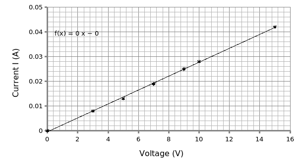
I=V/R. Theoretically, for ohmic conductors, on plotting the graph of I against V it should yield a straight line from the origin. From the graphical analysis, I=V/ (0.002822 ±3.307×10^-5). The reciprocal of the gradient (m) gives us the resistance of the resistor. Therefore R= 1/m= 1/ (0.002822 ±3.307×10^-5).
R= 354.35±4Ω.
According to electronic color coding, the resistor bearing orange, blue, brown and gold bands in that order is equivalent to 3*6*10±5% (360±18 Ω). On using a digital multimeter (DMM), a value of 354Ω is recorded.
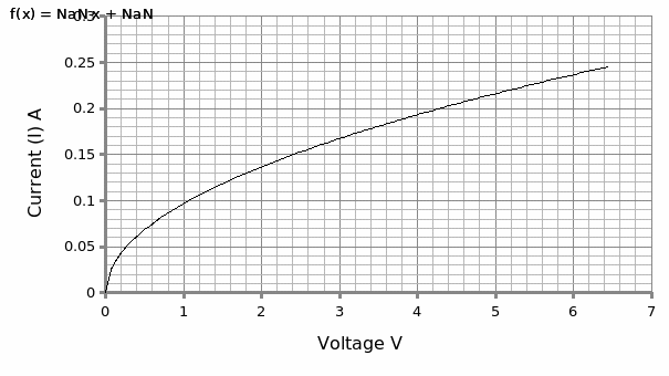
For the bulb, the nature of the curve is non-linear with the gradient decreasing from the origin. The average of the first five plots is equivalent to 0.071 A/V. Therefore the resistance R = 1/0.071 = 14.08Ω. The final five plots give an average R = 1/0.022= 45.45Ω. Conclusively, the resistance increases with increase in voltage.
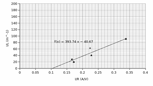
With respect to the effect of length on the resistivity of a conductor and, with the aid of the equation R=ρL/A (where R is the resistance, ρ is the resistivity, L is the length and A is the cross-section area of the wire), rearranging the equation (1/L= ρ/RA) and subsequently plotting 1/L against I/R gives a straight line.
Therefore; the gradient (S) = ρ/A= 393.7,
A= 0.002m,
Hence, ρ = 393.7*0.002
= 0.79Ωm.
Discussion and analysis
The preliminary objective of this experiment was to investigate the behavior of different types of conductors when subjected to varying voltages. From the first setup which involved a resistor of value 360±18Ω according to electronic color coding, the plot of current against voltage displayed a linearized plot. This, according to Ohm agrees with his laws which states that: “for ohmic conductors, the current (I) passing through a conductor between two points is directly proportional to the potential difference (V) between the two points provided other conditions e.g. temperature are held constant” (Weber 65). From the graph, the reciprocal of the gradient (354.35±4Ω) gave the value of the resistance which is consistence with the digital multimeter (DMM) (354Ω). Correspondingly, this value is consistent with electronic color coding which gives an approximate value of the resistance and as such, it cannot be used in accurate determination of resistance.
In the contrary, for the second setup which involved a light bulb, the plot displayed a non-linear plot. This, according to Ohms is a non-ohmic conductor. The resistance of the bulb as displayed by the graph increases with the increase in voltage. The bulb filament portrays this anomaly owing to the fact that its temperature increases with the increase in current triggering atomic vibrations responsible for increased resistance. This high temperature which is dissipated as heat by the filament is seen as a bright light by the bulb.
With regards to the factors affecting the resistance of a conductor and for this case length, the above plot (Graph 3) reveals that the resistance is proportional to length for a specific cross-sectional area. However, the value of the resistivity of the wire (0.79Ωm) is not consistent with the standard range specified for metals. This inconsistency has a bearing on the experimental errors that may include: irregular cross-section area of wire and, varying temperatures and pressure conditions. In future experiments, the former discrepancy can be eliminated through measuring the wire all rounds along the length. The later, can be minimized by monitoring the duo throughout the experiment to ensure consistency.
Conclusion
In a synopsis, the objective of the experiment was met since it was established that a resistor is an ohmic conductor while the bulb is a non-ohmic conductor. Moreover, it was established that the resistance of a conducting wire increases proportionately with the length for a specific cross-section area.
Works Cited
Weber, Bent. “Ohm’s Law Survives to the Atomic Scale.” Science Journal 335. 6064 (2012): 64-67. Print.