Introduction
Thermoelectric coolers are gadgets are made from junctions of two semiconductors of different materials usually stacked on top of each other (Anatychuk 1979, p.151). Thermoelectric coolers work with the Peltier effect, which is created by heat instability between the two semiconductor junctions (Vayner 1983, p.30). They consume electric current energy to transfer the heat against the heat gradient. One of the sides of the thermoelectric cooler junction absorbs heat energy when the electric current is passed while the other side dissipates energy in form of heat (Woodbury, Levinson, & Lewandowski 1995, p. 184). The main advantage offered by thermoelectric coolers over other conventional cooling apparatus is that their reliability is extremely high, their nature of being small is highly advantageous, and they are light in weight (Stockholm 1991, p. 228).
Objectives
- To understand the phenomenon of thermoelectric cooling
- To use thermocouples for temperature measurement
- To investigate the roles played by heat sinks, thermal paste, and insulation in the operation of a thermoelectric cooler
Materials
- Thermoelectric cooler assembly
- Heat sink paste
- Thermometer
- Brass, aluminum, steel, copper
Methods
Investigating the heat sink
Experiment 1: Effect of current on temperature difference created by a TEC
The thermoelectric cooler assembly used consisted of a thermoelectric cooler glued to a small heat sink using heat sink paste, without which the thermoelectric cooler would heat up dangerously even with small currents.
- The thermoelectric cooler assembly was attached to the copper heat sink using a thin coating of heat sink paste.
- The temperatures of both the cold surface of the thermoelectric cooler and the hot surface of the heat sink were measured as a function of current ranging from 0.0-1.0A.
- The thermocouple was covered in heat sink paste first before pressing them to the surface of the heat sink and thermoelectric cooler.
- Time was allowed for the temperatures to reach steady values after the current was changed. This was about one minute.
Results and analysis
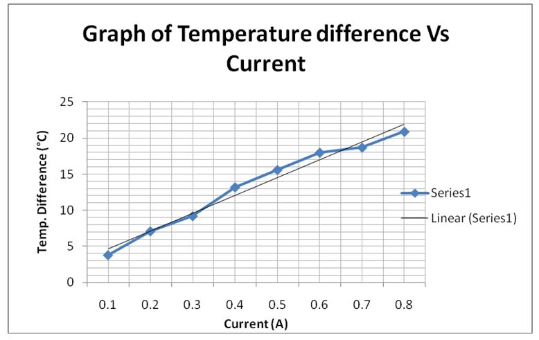
Table 1.0: Table showing Effect of current on temperature difference created by a TEC

The above table translated into the graph shows that the temperature difference created is directly proportional to the current that is passed through the heat sink. This means that the temperature difference increases with an increase in current. However, the limit that was used in this experiment was a current of 1.0 A in order to avoid damage to the sensitive thermoelectric cooler assembly.
Therefore, extrapolating the line graph, it can be found that the temperature difference created by the current of 1.2 A is 33.7°C.
Experiment 2: Effect of size of the heat sink
- The thermoelectric cooler assembly was attached to the various sizes of the aluminum in turn using the heat sink paste.
- The current was then fixed at 1.0 A and passed through the thermoelectric cooler assembly.
- The temperature of the cold surface of the thermoelectric cooler assembly was then measured three minutes after the current had been switched on for all the sizes of the aluminum.
- The heat sink and thermoelectric cooler assembly were at room temperature before the current was switched on.
Results and analysis
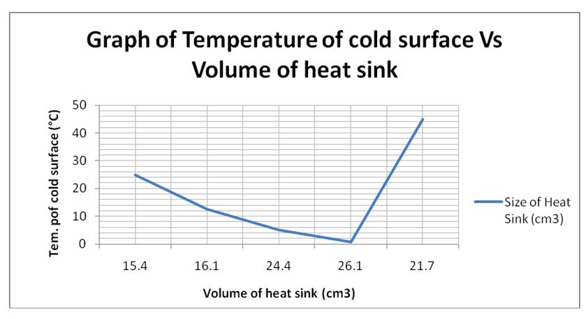
Table 2.0: Effect of size of the heat sink on the temperature difference.

The above graph shows that the temperature of the cold surface of the heat sink is much lower when the size in terms of volume, of the heat sink, is greater. However, this graph shows that the temperature of the cold surface to be 45°C when the volume is 21.7 cm3. This is an anomaly probably due to the measuring instrument and it does not follow the trend of the graph.
It can be concluded that the temperature of the cold surface of the heat sink is inversely proportional to the size (volume) of the heat sink up to a certain value when the temperature increases with an increase in the volume of the heat sink.
Experiment 3: Effect of heat sink material
Different materials were used for the heat sink in order to determine the type of material, which has an effect on the heat sink performance, and to determine the best material for the heat sink purpose.
- Several heat sinks of the same dimensions were used for this experiment. These include aluminum, brass, copper, and steel.
- The material which was best for use as a heat sink was established by passing a current through them
- The current through the thermoelectric assembly was fixed at 1.0 A.
- The temperature of the cold surface of the thermoelectric assembly was then measured after the current had been switched on for about three minutes.
Results and analysis
Table 3.0: Effect of heat sink material on temperature difference.
From the table above, it was evident that the cooling effect was more pronounced when the material of the heat sink was made of brass, steel, aluminum, and copper in that order. This implies that brass would make a very good heat sink material.
System design using thermoelectric coolers
- The experiment was done by initially using a small mass of water in the small copper container (Ccu =386 J kg-1 K-1).
- The temperature change of the water was measured after 4 minutes. This was also done for the thermoelectric cooler assembly.
- This procedure was repeated for different conditions including a bigger heat sink, the heat sink in ice, a smaller heat sink among others.
- The conditions that gave the best results for cooling the water for 30 minutes were selected and the temperature of the water Tw and the temperature of the thermoelectric cooler assembly Ttec was recorded after every 5 minutes.
Results and analysis
Table 4.0: Effect of different types of heat sink materials on the cooling effect of water.
Mw= Mass of water
Mc= Mass of colorimeter
dQ/dt= (MwCw+ McCc) dT/dt
dt= Tf- Ti (total time in seconds)
Table 5.0: Temperature difference created by one heat sink over time.
Volume of Aluminum= 40X 40 X4
Density of Aluminum= 2710 kgm-3
=6400 X 10-9 m3
Mass= Density X Volume
= 2710X 6400X 10-9
Rate of energy removal= 5J/s
dQ/dt= m* C* ΔT/Δt
Δt= 60s, ΔT=Tf- Ti, C= 900J/ Kg/ °C
-5= dQ= (2710 *6900* 10-9 *900 ΔT)/ 60
-5= 15.6 ΔT
-5= 15.6 (Tf-Ti)
-5= 15.6 (Tf-25)
15.6Tf= 390-5= 385
Tf=24.7°C
Three factors that might cause the temperature of the aluminum to fail to reach the final temperature you calculated in part 2 above include:
- Accuracy of measuring instruments
- Loss of energy due to dissipation to the air
- Prevailing room temperatures
Discussion and conclusion
The amount of current that passes through the thermoelectric cooler will determine the amount of heat energy difference created. The higher the current that flows through the TEC, the higher the temperature difference created. The size of the heat sink will also affect the temperature difference of the TEC. The bigger the size of the heat sink, the smaller the temperature difference created. Also affecting the efficiency and effectiveness of the TEC is the type of material used as the heat sink. The cooling effect decreases when the material used is brass, steel, aluminum, and copper in that order.
List of References
Anatychuk, L 1979, Thermo elements, and thermoelectrically devices, Prentice Hall, New York.
Stokholm, L 1991, Reliability of thermoelectric cooling systems, Oxford publishers, London.
Vayner, A 1993, Thermoelectric coolers, Prentice Hall, New York.
Woodbury, H, Levinson, L & Lewandowski, R 1995, Z-meters CRC handbook of thermoelectric, CRC Press, Inc., New York.