There is a substantial variety of sensors that differ in the values that they respond to and the technologies through which they operate. Resistive sensors are considered one of the most popular types because of their simplicity, which comes from their design. Its principle of operation is measuring the electrical resistance of a particular element, responding to changes in it via the different voltage produced. The resistance R can be calculated using the following formula: R = p*l/ A, where
- p – is the electrical resistivity of the material,
- l – is its length, and
- A – is its area.
When the resistive element is altered in some way, its resistance changes and the sensor records this difference. The simplicity and broad applicability of the approach have led resistive sensors to be used in large numbers of engineering applications.
The resistance of an object can be altered in a number of ways, and for most of these methods, there is a dedicated type of sensor. They are differentiated into four domains: geometrical (linear displacement, angle, strain), mechanical (force, torque, pressure, acceleration), magnetic (magnetic field), thermal (temperature), and optical (light flux). Of particular interest to this paper are sensors that deal with force, torque, and pressure, otherwise known as piezoresistors. They use materials that are responsive to stress, such as metals, alloys, and doped silicon. These substances are prone to deformation under pressure, causing their resistance to change. Generally, the following formula is used to describe the change: ΔR/ R0 = Gε, where
- ΔR – is the change in resistance,
- R0 – is resistance when not stressed,
- G – is the piezoresistive gauge factor, and
- ε – is the applied strain.
While piezoresistors can be manufactured from a large array of different materials, silicon is the most sophisticated and widely used for complex implementations. Through the usage of silicon, the size of the sensor can be minimized while retaining a substantial base resistance value, which is necessary to distinguish legitimate changes from fluctuations. Silicon also has a number of other advantages, but it struggles with temperatures above 150 degrees Celsius, for which materials such as SOI, pSOI, SOS, and SiC have been developed. Through the minimization of the sensor, it can be used for a number of different applications, such as gyroscopes. Currently, capacitive sensors are preferred over piezoresistive ones for that application because of their superior sensitivity and resolution. However, with recent advances in piezoresistive sensor technology, gyroscopes based on it may warrant consideration again.
The purpose of a gyroscope is to maintain a device’s orientation and angular velocity. The model proposed in uses four microscopic piezoelectric gauges, two of which detect Coriolis motion while the other two sense drive motion, which is one possible example. The formula for such a device would be as follows:
where
- ΔRs – is the resistance change,
- R – is the non-strained resistance,
- GF – is the piezoresistive gauge factor,
- σng – is the stress on the gauge (as opposed to the strain on the gauge
- Εng, E – is Young’s modulus of monocrystalline silicon,
- y – is the decoupling frame displacement,
- Гs – is the lever motion-deamplification factor, and
- L9 is the gauge length.
As can be seen from the successful implementation of the gyroscope, silicon satisfies the material requirements, namely a high mechanical quality factor, large coupling coefficient, and high mechanical strength.

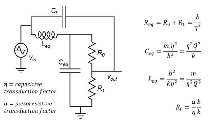
As shown in Fig. 1, a differential Wheatstone bridge configuration is used for the resonator, with vin being the drive AC actuation voltage and vout, the drive-motion sensed voltage. Using piezoresistive sensing, the resonator can dampen the vibrations within the gyroscope, enabling it to perform its functions in an improved manner. One of the most significant advantages of such an approach is its size, which can be minimized to nanoscopic levels and implemented in a range of electronic devices. One notable advantage of this model is its reduction of feedthrough, which estimates as three orders of magnitude lower than it would be for a comparable capacitive sensor. With that said, this advantage is theoretical in nature and needs additional testing before it can be confirmed.
While the proposed gyroscope has been tested to a substantial degree, there is not enough evidence yet to warrant widespread practical implementation. With that said, this design has demonstrated its effectiveness, approaching the theoretical thermomechanical limit of the achievable angle random walk despite the low cost and large pressures. As a result, it has been able to measure Earth’s rotation rate in an accurate and stable manner through gyroscope carousing over a period of over 1000 seconds. They have also shown a degree of resilience against drops, changing their sensitivity by less than 0.8% after ten free drops on marble. As such, the gyroscope appears to be promising for practical implementation and mass production, able to produce a high performance at a low cost while also capable of operating in a variety of circumstances. With that said, the current designs are proofs of concept rather than complete devices ready for mass production, and a substantial amount of further research and refinement is necessary.

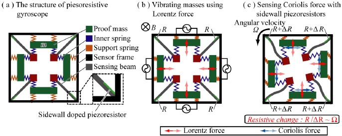
Another potential design for a piezoresistor-based gyroscope is displayed in Fig. 2, using four sidewall-mounted doped piezoresistors that synchronously oscillate using the Lorentz force. The purpose of this design is to measure in-plane beam deformation generated by the Coriolis force that results from angular motion, which is challenging if using surface-mounted piezoresistors. The gyroscope is placed within a magnetic field to generate the Lorentz force necessary for the oscillation to occur. Testing has shown that, when powered and placed within a magnetic field, the gyroscope is able to accurately report the angular velocity to which the unit is subjected. On the other hand, when either of the two conditions was absent, there was no signal from the gyroscope, indicating that it operated according to theory. The advantage of this gyroscope over the one proposed above is that it is less complex to manufacture because of the structure of the nano-gauge.
This variation of the gyroscope presented above is in-plane, operating only in two dimensions. While adequate as a proof of concept and in some specific applications, it is not necessarily suitable for operation under all circumstances. However, a triaxial variation using the same technology along with surface-mounted piezoresistors has been proposed since, demonstrating accurate three-dimensional angular velocity responses with low crosstalk. Depending on what axis the angular velocity is oriented along, the resistance changes of specific beams in the sensor will individually increase or decrease, enabling the sensor to determine the direction of the rotation using the following formula:

where Ωx, Ωy, and Ωz are angular velocity components corresponding to each axis, a is a multiplier derived from the sensor’s characteristics (107 in the test conducted in), and Ri and ΔRi are the resistances of each of the four respective beam and changes in said resistances, respectively.
The new designs have been able to alleviate some of the weaknesses of piezoresistive gyroscopes and present a compelling alternative to capacitive sensor-based ones. They do not have the issue of parasitic capacitances or feedback resistance noise, which, among other factors, lets them display and angle random walk ten times superior to that of capacitive gyroscopes under the same circumstances. Moreover, they also display superior resistance to vibrations, tested across five different piezoresistive and capacitive gyroscopes. Overall, the technology appears to have overcome at least some of its shortcomings and warrants consideration for practical implementations in the future.
While resistive sensors are among the most common types used across different tools and devices, the technology has not been explored to its limits yet. New technologies and implementations emerge, leading them to become viable in a range of roles. In this case, piezoresistive gyroscopes, while rejected in the past due to their inferiority when compared to capacitive ones, appear to have addressed their problems. Their advantages, both innate and created out of engineering innovation, enable them to outperform currently used models by substantial margins without a corresponding increase in cost. As such, the technology warrants extensive research, consideration, and potential implementation, particularly due to the ubiquity of gyroscopes in modern technology.
References
B. George, J. K. Roy, V. J. Kumar, and S. C. Mukhopadhyay, Advanced Interfacing Techniques for Sensors: Measurement Circuits and Systems for Intelligent Sensors. Cham, Switzerland: Springer International Publishing, 2017.
E. Dertien and P. P. Regtien, Sensors for Mechatronics, 2nd ed., Amsterdam, Netherlands: Elsevier Science, 2018.
R. H. Bishop, Ed., Mechatronic Systems, Sensors, and Actuators: Fundamentals and Modeling, 2nd ed., London, United Kingdom: CRC Press, 2017.
S. C. Mukhopadhyay, K. P. Jayasundera, and O. A. Postolache, Modern Sensing Technologies, Cham, Switzerland: Springer International Publishing, 2018.
S. S. Ge and F. L. Lewis, Eds., Autonomous Mobile Robots: Sensing, Control, Decision Making and Applications, Boca Raton, FL, USA: CRC Press, 2018.
S. Dellea, P. Rey, and G. Langfelder, “MEMS gyroscopes based on piezoresistive NEMS detection of drive and sense motion,” J. Microelectromech. Syst., vol. 26, no. 6, pp. 1389-1399, 2017. Web.
K. Uchino, Ed., Advanced Piezoelectric Materials: Science and Technology, 2nd ed., London, United Kingdom: Elsevier Science, 2017.
S. Dellea, G. S. Strazzeri, P. Rey, and G. Langfelder, “Ultra-low-voltage gyroscopes based on piezoresistive NEMS for drive-motion and Coriolis-motion sensing,” presented at the IEEE 30th International Conference on Micro Electro Mechanical Systems (MEMS), Las Vegas, NV, USA, 22-26, 2017, pp. 21-24.
S. Dellea, F. Giacci, A. Longoni, G. Langfelder, P. Rey, and P. H. Robert, “Analysis of gyrocompassing through miniaturized MEMS based on piezoresistive sensing,” presented at the IEEE International Symposium on Inertial Sensors and Systems, Laguna Beach, CA, USA, 2016, pp. 25-28.
S. Dellea, F. Giacci, P. Rey, A. Capodici, and G. Langfelder, “Reliability of gyroscopes based on piezoresistive nano-gauges against shock and free-drop tests,” presented at the IEEE 29th International Conference on Micro Electro Mechanical Systems (MEMS), Shanghai, China, 2016, pp. 255-258.
K. Abe, H. Takahashi, T. Takahata, and I. Shimoyama, “In-plane gyroscope using a piezoresistive beams with sidewall doping,” presented at the IEEE 32nd International Conference on Micro Electro Mechanical Systems (MEMS), Seoul, Korea, 2019, pp. 680-83.
H. Takahashi, K. Abe, T. Takahata, and I. Shimoyama, “MEMS triaxial gyroscope using surface and sidewall doping piezoresistors,” Journal of Micromechanics and Microengineering, vol. 30, no. 10, 2020. Web.
F. Giacci, S. Dellea, and G. Langfelder, “Capacitive vs piezoresistive MEMS gyroscopes: a theoretical and experimental noise comparison,” Procedia Engineering, vol. 120, pp. 406-409. Web.
F. Giacci, S. Dellea, and G. Langfelder, “Signal integrity in capacitive and piezoresistive single-and multi-axis MEMS gyroscopes under vibrations,” Microelectronics Reliability, vol. 75, pp. 59-68, 2017. Web.