Introduction
The construction industry adopted specialized technologies in the design and management of projects. Activities in a building are established after the modelling stage, in which prototypes imitating real objects to be made in the project are created and assessed. This is done through Building Information Modelling (BIM), which integrates the entire life cycle of a project (Rui 83). In building, sculpting serves as a reference mostly because systems and processes are highly linked up. The demonstration is done through various software, which will be discussed later in the paper. Using BIM in engineering projects reduces cost, improves teamwork, and lessens risks and expenses. Application of software is relevant in simulation and visualization of project scope, schemes projection, and monitoring of changes in plan in terms of cost and design.
However, despite the numerous benefits related to BIM, they are associated with a couple of risks due to human errors, inefficient communication, and prototype setting techniques. Project managers should avoid relying on software models and consider deficiencies that could exist in the process (Patil et al. 2775-2780). Moreover, decision-making in firms that apply software design is complex due to diverse opinions from many parties. Different models have unique functionalities, and therefore, project managers can integrate them to increase construction efficiency. This report will be focusing on the five-modeling software and construction of the Kosciusko bridge in New York and will finally compare two projects in the USA.
2D Modelling Software
The 2D model is the most basic demonstration used in construction; it is applied in cutting shapes, especially in sheet materials. It involves vector art programs that utilize mathematic equations and geometrics, that is, points, shapes, and lines (Liu et al. 4). Programs in 2D are used in engraving through digital fabrication, for instance, laser and vinyl cutter and router. 2D vector graphics give machines instructions and are created using different software applications or downloaded from various digital sources.
The 2D model involves only two-dimensional components to assess the vertical and horizontal axes. It displays objects in height and length as to if they lie on a flat surface and do not express the depth. Each application for 2D is associated with different features in terms of cost, ease of use, capabilities, background information, portability and output, and operating system platform. Among the available software in 2D modeling are Gravit designer, Adobe illustrator, Google drawings, CorelDRAW, Inkscape, Rhino 2D CAD, and AutoCAD.
3D Modelling Software
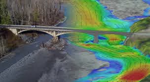
The 3D model is a three-dimensional space in which three elements of measurement, width, length, and height, are considered. It also comprises details on the relationship, geographic info of the building, and geometry. 3D is effective because it identifies and eliminates errors from 2D drawings (NT par.1-6). The model takes two major forms, first, as a design model in architectural, structural, site, and MEP, mechanical, electrical, and plumbing functions. Second, as a construction model in breaking down design simulation into building sequences.
Application of 3D begins in site planning, which is the first stage of the building project. This step involves determining the location’s entrance, establishing the fence (temporary), location of the tower crane, generator, hoister, water tanks, and other essentials in a workplace. The 3D demonstration shows the relationship of real facilities and tools in virtual space. It helps the contractors plan the space according to the location’s condition and optimize the area, equipment, and material stores. From a 3D model, the site’s correct layout is obtained, and a feasible construction plan is established.
Example of a 3D Home Model
The Icon is the first US company to permit 3D print homes. They use 3D printer Vulcan to print houses of 600800 square feet within a day. Vulcan II is efficient and requires approximately six people on the construction area to operate and lead the project (“Best Airport/Transit and Project of the Year Finalist: LaGuardia Airport, Terminal B Arrivals and Departures Hall” par. 1-5). They also use built-in CAD in planning and provide pre-print visualization for their clients. Icon has also developed a system for material handling and delivery known as Magma. The most available software for 3D modelling includes Sketchup, Blender, AutoCAD, Rhino, Revit, Maya, 3Ds Max, and many others.

4D Modelling Software
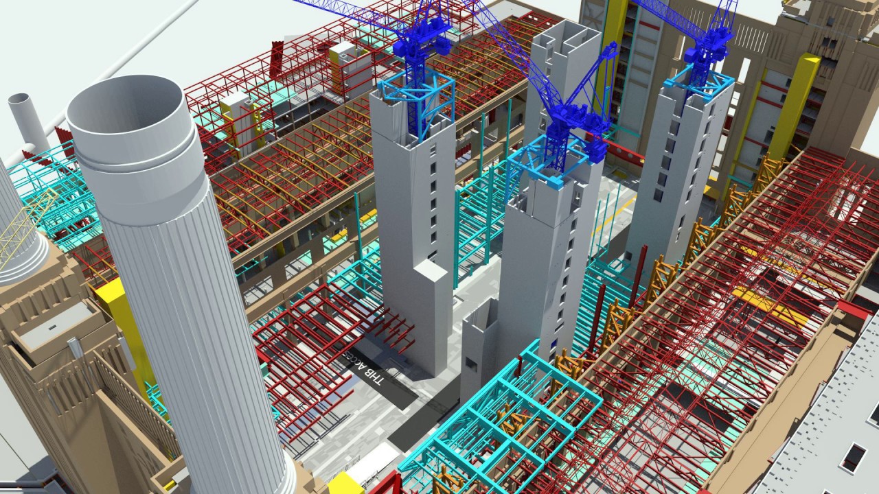
4D is a model in which a 3D demonstration of a construction project is linked to scheduling through a suitable software program, displaying a project’s simulations in a 4D environment. In this prototype, business activities are visualized at a given time duration, which can be seen in 3D (Peterson et al.). Time schedules use the process daily, and monthly, clients can plan their projects effectively. 4D detects clash issues between special parties in a building and communicates them for modification to prevent construction collision risks, which causes delays.
In engineering projects, 4D is applied in management to monitor the time of entrance in the location, workforce, materials, tools, and other vital resources. It provides work schedules guiding every section in the process. This model’s essential feature is the powerful visualization and an efficient tool for communication between participants (Pham par. 1-3). It is easy for the members to monitor the project’s critical path since all the information they need, work schedules, process, and time is available. Additionally, this model assists in safety control on the site through hazard analysis from which a safety design is suggested. It also comprises accident examination and simulation software, which detects disasters before they appear (Balakina et al. 1). This helps establish a first aid plan and rescue workers in case of an accident, especially during the installation of steel components.
Example of Software and a Picture
A good example of a company using this model is 4D Construction LLC, located in Coral Gables, US. The company has only five employees across all the locations. The most common 4D software are Navisworks, Synchro, ArchiCad Navigator, Itwo, and Vico
5D Modelling Software
5D can be defined as a model in which a 3D prototype is connected to schedule and cost using favorable software. It is applied in budgeting, which increases performance throughout the construction process. In the 5D model, it is possible to calculate the project’s cost, which is useful in rating the financial execution during the actual process. Contrary to the traditional method of project management in which quantity survey was difficult and considered a waste of time, a 5D model, is efficient and accurate (Rui 84). Originally, the QS calculation was done manually using CAD documents, which stored limited data and was prone to deviation due to human error. 5D model generates an updated quantity survey, even after modification of design. The software reduces potential manual errors and reduces the waste of reinforcement used in construction. By analyzing the steel ratio of a building and use of Radio Frequency Identification, a firm can enhance leftover management and determine the recyclable materials in the site.
Example and Picture
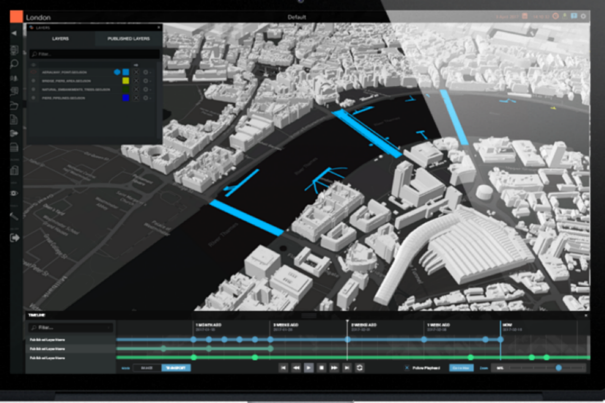
Examples of 5D software available include LOD Planner, Bimobject, Avail, Unifi, MagiCAD, Sketchup, Autodesk Revit, ArchiCAD, Vectorworks, Aecosim, Allplan Tekla, Solidworks, RhiniBIM, Autodesk fabrication, Dynamo, Grasshopper, Hypar, Exgenerative design, Edgewise, Sefaira, Green Building Studio, Bim 360, Trimble Connect, ALLPlan BIMPLUS, ArchiBus, YouBim, and many others. Cityzenith is a good example of companies using 5D demonstrated in their 100 new city model. The model gives information on the project and other relations such as road networks, weather, traffic, satellite imagery, and other infrastructural layers.
6D Modelling Software
A construction project involves many processes from disparate people, and therefore, the project manager requires a system that can control the entire process. The traditional techniques used in building comprised information from numerous suppliers and contractors, which was recorded manually. The data was prone to error, and handing over was ineffective, increasing the chances of project failure. With 6D, more information about the project operation and maintenance are available (Montiel-Santiago et al. 5731). Additionally, the software is used jointly with RFID facilities and label chips, which helps the operators obtain important data in the building faster and clearly.
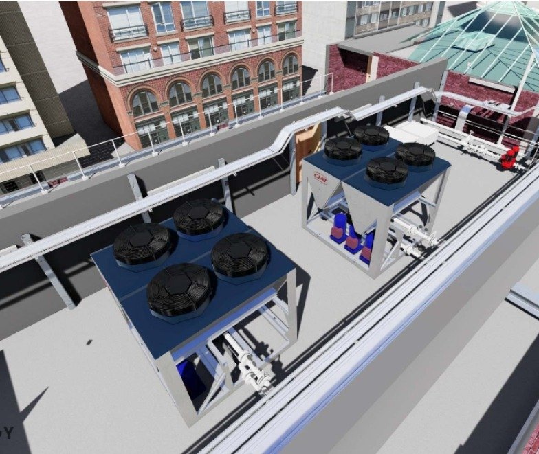
Throughout the building service duration, various facilities and structures must be maintained constantly to improve the project performance while reducing the total maintenance cost. Examples of such equipment include façade, water supply, electricity connection, firefighting scheme, beam, among many others (Pucko et al. 1-4). 6D is applied today in green construction to evaluate and assess the project’s compliance with the government and owner requirements. Some specifications are given concerns about energy consumption, lighting, air flow (internal and external), natural ventilation, crowd flow, and many others. This model works better with software for professional construction system analysis to verify energy usage according to the design’s sustainability standards and regulations.
Example of a 6D Structure Model
An example of a company using a 6D model is Karno Energy Engineering. The company applies 6D tools such as Revit Program in their construction projects. 6D applications design digital building prototypes that have details on the environment and other external influences on a project. They also use 6D bim in the analysis of the erection process and the project’s life cycle. This model’s simulations are used to obtain real-time insights into the system and determine time-consuming practices inside the construction site. The most available software includes Autodesk and Revit.
Kosciusko bridge (New York) Project
Kosciuszko Bridge, or the K Bridge, is traverse Newtown Creek and Queen’s vis the Brooklyn –Queens headed to the west. It was built in two phases, an eastbound bridge completed in 2017, and a westbound finished in 2019. It is the first cable-stayed bridge in the united states and consumed a significant amount of resources. The bridge was built to counter traffic in the old one, which had become a problem in the state. Among numerous available designs, the New York State Department of Transportation was selected cable-stayed due to its ideal aesthetic and long span. Phase 1 was designed by HNTB Corporation, under the joint venture of Skanska USA-Kiewit Corp. and ECCO III Enterprises Inc. (SKE). Step two was planned by WSP USA and build by Granite Construction Northeast Inc.
The first phase heading to the east, Brooklyn to Queens, was a complex problem considering the heavy traffic in that region.

The project had financial constraints due to limited funding. Therefore, the contractors had to look for ways to prevent schedule delays, reduce risks, and minimize the project’s costs for it to be successful. They used a unique approach to manage the project using data models, which incorporated costs and schedule in a visual simulation of the building phase. The method utilized a 3D model in conjunction with 4D and 5D designs to ensure time and money are taken into account. According to the project’s request for proposal, a 2C CPM schedule was demanded. CPM schedule used had a cost-loading component, and a 5D model was a compulsory feature for a contractor.
The 5D model was used in tracking the project and in the issuance of interim payments, which were parts of a lump-sum payment for different items. Additionally, the project utilized a visualization model in the evaluation and monitoring of the planned activities. Overall, the bridge’s establishment required 3D,4D, and 5D models to accomplish the construction’s key elements. In the project, the 3D model was a virtual design containing an illustration of physical objects as surfaces (The US Government and New York State Department of Transportation). It included 3D animations and simulations from the 4D schedule which served as a visual aid in the evaluation of proposals and public outreach.
During the development of 3D models, which served as a support to the 4/5D they used, Bentley and MicroStation format. Coast loaded progress schedules were developed and maintained by Oracle and Primavera software through P6 arrangement. Lastly, in developing 4/5 D prototypes and simulations, the contractor used Synchro and Professional / Autodesk Navisworks modelling software. Additionally, the project deployed SpringBoard data software as a host for the cloud service and a computer-aided design drafting (CADD) standard. All the software packages adopted in the construction were newly acquired and not owned by the agency until the project finished.
In addition to the Software requirements, the department of transport established a strategy for maintaining the models, tracking the software in use, change management, and quality control. CADD served as a contact for all activities related to modelling and simulation while still helping the managers in directing, scheduling, animation, and other responsibilities. Since the use of 5D is new in the industry, contractors conducted workshops to understand the model’s logic. Designers also established 2D CADD drawings, which were later converted into 3D model essentials.
However, during the project, various challenges were encountered by the department of transport and the design-builder. First, it was difficult for them to meet all the requirements to store and update modelling files via the SpringBoard server. Various software packages for updating 4D and 5D models were loaded. The second challenge regarded Synchro files’ size, which exceeded the capacity and bandwidth of the project’s server. Synchro’s frequent updates were required, yet it had to be completed by the running service on the same server.
There were other technical issues associated with the systems; for instance, in the system’s presence, the workers had to wait for it to be resolved before they could continue working. The team solved the problem by running the Synchro software from a different local machine and saving the files on the server frequently, providing 4D animations by the end of every month. Another issue emerged because the designs were established using 3D models, which were created from 2D drawings. The design process developed was inefficient, yet the team used many software packages.
From the project, the participants and the general public learned various lessons. First, before adopting any model or system in a project, team members should be trained appropriately and timely. Second, in any project, staff selected should be dedicated to the project and have the necessary technical skills to create and maintain models. Third, 3D design features should be established on time to accommodate all the requirements in 4D and all investment understood to gather the infrastructure and skills necessary. Lastly, in complex and capital-intensive projects such as the K Bridge, it is crucial to have a full-time scheduler on the building’s location.
Construction of LaGuardia Airport new Terminal B arrivals and Departure Hall
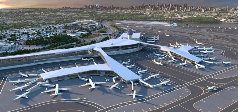
Another recent US project that has deployed current technology is the construction of LaGuardia Airport’s new Terminal B arrivals and Departure Hall. The $4 billion projects were initiated to reduce the number of passengers who used the airport, which had increased significantly over the years. The construction was under Skanska and Walsh’s partnership and was among the complex projects done in the firm. The building team responsible for the project utilized the current technology to bring the resources and goals of the institution to fruition.
The contractors deployed disparate systems ranging from aerial photogrammetry to a 4D model of scheduling. They also used various 360-degree cameras, which produce over 15,000 capture pictures in every construction. Another technology used is laser scanning, which helped ensure the built environment are in line with the original 3D model of the project (ENR New York). A base map of the site was created using photogrammetry, which assists in the extraction of 3D info from the photographs taken. One challenge in the project was limited airspace, which could not allow the use of drone operators. The base map was loaded into 3D model, and specific details were obtained by the 3D laser scanner, which ensures that constructed objects conform with 3D BIM plan. The laser-assisted the construction team in capturing details of the facility without compromising the functioning of the airport.
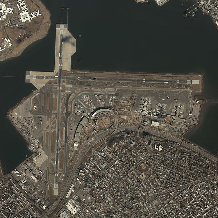
To ensure that collision was prevented in the construction process, different handling systems were established supported by numerous individual motors. The system is more than 7 miles passing through ceilings and walls such as a roller coaster. Contractors used a 3D BIM model, which was spread to the subcontractors on the site to prevent clashes on the baggage system operation. Space was reserved for every activity before the process commencement. The progress of construction was captured by cameras and distributed to people on the site for monitoring.
Comparison Between (Kosciusko Bridge and Construction of Laguardia Airport New Terminal B Arrivals and Departure Hall)
The two projects in the US applied various technologies under different designers and project managers. Despite the differences in the scope of the activities in them, the two projects are similar in many ways. The two projects were under the transport ministry, and their main objective was to counter traffic in the respective locations. During their initial stages, the tasks used 1D model for their research, which required details on government regulations, weather, existing conditions of the previous and existing facilities, estimation of area for the construction, consulting of experts, selection of software and design to be used I the real project.
After the research point, the projects deployed 2D models to draw images of the expected features and facilities, documenting the components of the project and selection of programming and communication channels. Using the 2D scope, the project managers established the content of the task, materials needed, structures, energy and the overall sustainability of the project. 3D model used in the two projects were from different software. For instance, the airport construction used laser scanning to obtain details from photographs. They also used python programming, programs of clash detection after which documents were presented regarding the project and its sustainability. Another common feature in the two tasks was their usage of 4D modelling in conjunction with a 3D prototype. The two projects used simulations in scheduling the project, planning, timelining and visual validation. Life cycle simulations helped in identification of critical path in both projects and ensured the actual construction went as per the plan established.
Construction of the airport did not use 5D model in its task while the bridge did. Contractors in the Kosciusko bridge applied 5D in costing and issuing contracts to the bidders. The project manager had a chance to enhance the project’s efficiency through fabrication models and analysis of the cost of the lifecycle. None of the projects used 6D in evaluating the performance of the facilities, probably because of the two is in the transport industry in which outcomes can hardly be quantified.
Summary
Application of business information modelling in the construction and building industry is associated with numerous benefits which revolve around cost and efficiency. Project managers today use technology to lead various activities on the site. This does reduce not only the number of employees required in project implementation and management but also shorten the time needed for different parts. There are various modelling software’s established by other companies for the execution of specific models. Models used in construction include 1D, which is used at the beginning of the project for conduction research, consulting of the experts and designing of the task.
The second model is 2D, also known as the vector, applied in the production process, implementation, database development and sustainability of the project. Another prototype is 3D which comprises of the shapes and used in representation, implementation of 2D drawings preparation of the final document of design, and sustainability concerns of the construction. The fourth model is 4D, in which the primary consideration is time. It is used in production scheduling, development of systems and simulations.
5D is the next model in the hierarchy, whose main factor is the cost of the building project. The model is applied in the production process, contracts development and awarding, and sustainability. 6D prototype, although not involved in all schemes, takes into account the performance of the assignment. It is used I evaluation of results, value engineering, save estimation and re-designing where appropriate. Some construction firms use a 7d model which is still unpopular, in efficiencies management.
Large construction projects, such as construction of highways, airports and storey-houses, utilize the modelling techniques to ensure all aspects of the development are safeguarded. However, the models are associated with many challenges especially because construction industry has not been using them. Only few workers in building sector are familiar with the software used in prototyping, and therefore, intensive training is needed before commencement of any project. If proper preparations are made for the applications, construction firms can reduce their cost, time and improve the overall performance of the project.
Works Cited
Balakina, Anastasya, Simankina Tatyana, and Lukinov Vitali. “4D Modeling in high-Rise Construction.” E3S Web of Conferences, vol. 33, no. 5, 2018, pp. 1-5.
Beilin, Holly. ‘Home Building Startup New Story Unveils 3d-Printed House at Sxsw to Shelter the Developing World.” News Stories, 2018. Web.
“Best Airport/Transit and Project of the Year Finalist: LaGuardia Airport, Terminal B Arrivals and Departures Hall (Headhouse).” ENR New York, 2020. Web.
Bosquin, Joe. “How Wide-Ranging Tech Propelled Skanska’s $4 billion LaGuardia Airport Renovation.” Construcion Dive, 2020. Web.
Karno Energy Engineering. Smart House- How to Increase Energy Efficiency. 2020, Web.
Liu, Mingqiang, et al. “System Dynamics Modeling For Construction Management Research: Critical Review And Future Trends.” Journal of Civil ngineering and Management, vol. 25, no. 8, 2019, pp. 730-741.
Montiel-Santiago, Francisco Javier et al. “Sustainability and Energy Efficiency: BIM 6D. Study of the BIM Methodology Applied to Hospital Buildings. Value of Interior Lighting and Daylight in Energy Simulation.” Sustainability, vol. 12, no. 14, 2020, p. 5731.
Morris, Sebastian. “Rendering of the Newly Expended LaGuardia Airport.” New York YIMBI, 2020, Web.
NT, Baiju. “Top 12 manufacturers of 3D printed houses and buildings.” Roboticsbiz, 2020. Web.
Patil, Deepa. A. et al. “Application of Building Information Modelling Software’s for Planning.” International Research Journal of Engineering and Technology (IRJET), vol. 4, no. 7, 2017, pp. 2775-2782.
Peterson, Jim, et al. “Delivering a Masterpiece.” The Magazine of the American Society of Civil Engineers, 2020. Web.
Pham, Kieu-Trang, et al. “4D-BIM-Based Workspace Planning for Temporary Safety Facilities in Construction SMEs.” International Journal of Environmental Research and Public Health volume 17.no.10, 2020, p.3403.
Pučko, Zoran, et al. “Application of 6D building information model (6D BIM) for business-storage building in Slovenia.” IOP Conference Series: Materials Science and Engineering, vol. 245, no. 6, 2017, pp.1-10.
Rui, Yin. “Review of Building Information Modeling (BIM) Application in Construction Industry.” International Journal of Innovative Technology and Exploring Engineering, vol. 8, no. 6, 2019, pp.83-86.
Smart Cities World News Teams. ‘Smart city model of London on City zenith’s Smart World Software Platform.’ Smart Cities World, 2020. Web.
The US Government and New York State Department of Transportation. 3D Engineered Models: Schedule, Cost and Post-Construction: Program Case StudY 4D and 5D Modeling: NYSDOT’s Approach to Optimizing Resources. (n.d.).