Introduction
The design of a solar-powered water cooler is based on the normal components and operations of cooling systems. A solar-powered water cooler has two major parts. These include the cooling unit and heat source. The water uses the thermodynamic cycle in the same way as electricity-powered conventional generators. On the other hand, the solar heat source is designed using a flat plate with a focused collector to concentrate solar energy and supply it to the device.
The coefficient of performance will be used as the performance evaluation index. It refers to the ratio of cooling provided to heat supplied (Abbad et al. 1228). The cooling component, as well as the cooling ratio, can be defined as follows:
- Cooling ratio = Heat absorbed by coolant during cooling/Heat absorbed by the generator contents during the cooling
In order to define the performance of the solar collector, a heating ratio is determined as follows:
- Heating ratio = Heat absorbed by the generator content/Incidental solar radiation on the collector
The product of the above two ratios defines the overall performance ratio of the solar-powered water cooler as shown in the following equation:
- Overall performance ratio = Heat absorbed by coolant during cooling/Incidental solar radiation on the collector
During the analysis of the designed water-cooler components such as the collector and generator, the concepts of cooling ratio and heating ratio will be essential (Choudhury et al. 559).
Countries that lie within the latitude of the tropics receive direct sun, and solar radiation is evenly distributed throughout the year. Many countries within the tropics are developing in terms of economy. Their infrastructures are still poor and the supply of traditional electricity is limited, especially in rural areas. Conservation of water resources in the area is highly needed. Even though normal refrigerators are available at affordable rates, a limited supply of electricity hinders their use.
The design of a solar-powered water cooler will help in providing water-cooling services to the people in rural areas as they make use of the abundant supply of solar energy throughout the year. By creating a successful solar-powered water cooler design, a long-lasting solution will be provided to enhance current water-cooling systems (Parash, Baredar and Mittal 39).
Ideal Cycle Analysis
In the ideal cycle analysis of the ammonia water absorption approach, the main assumption is that all thermodynamic processes are reversible. Figure 1 and figure 2 below show the principle operation of the solar-powered cooler. The first figure is used to show the operations of the cooler during the regeneration phase, while the second figure illustrates its operations during the cooling phase. In this context, the transfer of energy occurs in the form of heat at three different levels of temperature.
The first level is the atmospheric temperature denoted by Ta. At this temperature, the device’s condenser and absorber reject the heat. Another temperature level occurs where the device takes heat from the cold chamber; it is denoted by Tc (Abbad et al. 1234). The third level of temperature occurs when the generator receives heat, and this is denoted by Tg.
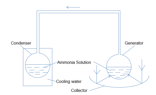
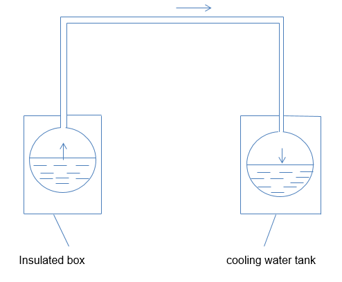
To understand the ideal cycle analysis, we can use the equivalent machine to create an expression for the same. The arrangement indicated in figure 3 below provides an illustration of a machine’s reversible performance, which corresponds to that presented in the absorption plant for water cooling. In this context, a reversible heat engine gets heat energy whose quantity is Qg at the temperature Tg (Choudhury et al. 563). The heat is rejected at the temperature Ta, at which point the work whose quantity is Wga is produced, as shown in the diagram below.
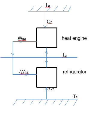
Based on the above diagram we can model the following equation.

In the above equation (i), all temperatures are determined using the thermodynamic scale of temperature. On the one hand, a reversible cooler receives heat quantity Qc at Tc. The rejection of the heat occurs at a temperature of Ta. On the other hand, the absorbing quantity of work is denoted by Wca. Coefficient of performance based on the above figure 3 can be expressed using the equation (ii) below.

Supposing Wga is made equal to –Wca, then the developed plant in figure 3 above will be equivalent to the absorption cooler. Consequently, the combined coefficient of the plant will be defined using Qc/Qg. Combining the two equations gives the following expression:

The practical importance of the above equation is that it is possible to calculate Ta if Tg is known. In this case, the Ta is given a fixed value, but the designer chooses the convenient value of Tc.
Design of the Solar-Powered Cooler
Configuration Choice
As specified previously, a solar-powered water cooler has two constituents, the heating unit, and the cooling unit. The solar energy unit operates based on the flat plate collector. It is a flat-surfaced panel that absorbs direct sunlight radiation and diffuses it. To control heat loss, the plate has a transparent cover and an insulation material. The plate absorbs solar energy and the energy is changed into heat. Subsequently, the heat is removed in the form of steam or vapor (Parash, Baredar and Mittal 44).
The most suitable device for this experiment is the flat plate collector placed in a fixed position. Moreover, it is more affordable, compared to the focusing or parabolic collector. For the purposes of the study and the fact that the experimental design targets a rural area without electric power, the intermittent absorption cooling system is the most appropriate.
Alternating Cooling
The alternating cooling cycle involves two key operations, regeneration and cooling. Regeneration occurs when the coolant-absorbent fluid heats with the aim of driving off the coolant vapor and condensing it in a different container. Cooling occurs during the vaporization of the coolant liquid and this creates a cooling effect in the evaporator. In contrast, the absorbent re-absorbs the coolant. To enhance the simplicity of the experimental device, the condenser will work as the evaporator while the generator will work as the absorber.
Operation of the System
To understand the operation of the solar-powered water cooler system, see the diagram in figure 4 below.
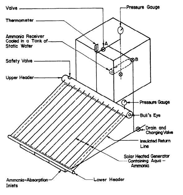
The above diagram is useful in illustrating the regeneration and cooling cycles of the system. The valves A and B play an important role during heat cycles. When regeneration takes place, valve A opens while valve B closes. The flat-plate collector supplies heat to the strong solution in the generator and produces steam at high pressure. The insulated pipes transport the weak solution from the top-header to the device’s bottom-header. Since water has lower volatility than ammonia, the top header vapor has a higher concentration of ammonia than water.
The ammonia vapor then passes into the system’s condenser, immersed in a cold-water tank to maintain a low temperature (McCarney et al. 35). During the process, the pressure remains uniform in the entire system. Valve A closes when the heating stops, and this causes a reduction in vapor pressure within the generator. The ammonia concentration in the generator is now less, compared to how it was before.
It is important to remove the cooling tank before refrigeration occurs, and this would cause valve B to open. At this point, the condenser now operates as the generator. The ammonia solution changes into vapor due to the fact that the pressure difference is enhanced between the generator and evaporator. The device’s evaporator supplies the necessary heat energy for the vaporization of ammonia. This helps in producing the desired cooling effect.
The ammonia gas is taken to the generator’s bottom head through the pipe for the incoming vapor facilitates the absorption. This completes the full cycle of operation. In order to accommodate the intermittent availability of solar power, cooling occurs during the day, and regeneration occurs during the night when solar power is unavailable.
Regeneration Phase
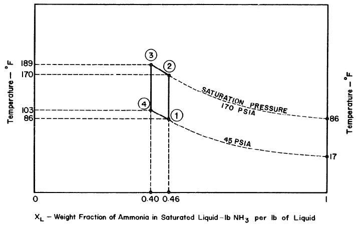
From figure 5 below, the temperature of the condenser is 86°F and the saturation of pressure of dry ammonia at the same temperature is 170 Pa. It is possible to determine the point 2 of the thermodynamic cycle because its pressure and the ammonia concentration are known. On the other hand, point 3 has a fixed value at the maximum temperature achieved by the collector, which is 189°F. The values are used to determine point 3 as well as the concentration of the solution, which is 0.40.
Cooling Phase of the Cycle
In an ideal context, the cooling or refrigeration phase entails that the cooling of the solution is done at a pressure of 45 Pa. when the concentration is 0.40 at a temperature of about 103°F. This is defined at point 4, and the cooling cycle becomes complete through the 4-1 process when ammonia vapor is turned into a solution at a temperature of 170°F.
Specifications of Collector and Generator
The specifications of the collector and generator of the water cooler determine the compactable level of the system (Maxime et al. 118). Therefore, the collector-generator area will be 1.2 meters by 1.2 meters. Black-iron pipes are used in order to control the corrosion aspect and the issue of high pressure, which is related to concentrated ammonia solution. A 1.2 meter by a 1.2-meter copper sheet with a thickness of 18 millimeters will be chosen as the collecting plate.
To prevent the dissipation of the collected solar energy, the plate will be painted black. The plate is soldered with 12 tubes having diameters of 25mm at an interval of 0.1 meters. To enhance the effective separation of water from ammonia vapor, the design will use a 0.1-meter pipe for the top header. This 1.42-meter-long pipe will provide a liquid surface area of 0.145 meters squared whenever the header is half full. A pipe 50 mm in diameter and 1.37 meters long will be used for the bottom header. The diagram in figure 6 below shows the arrangement of the collector and generator (McCarney et al. 38).
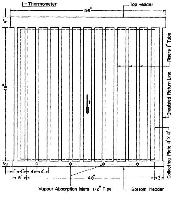
In order to prevent the heat loss at the back of the collector and generator, 0.1-meter thick polystyrene foam will be used as the insulation material. Thermal insulation materials will also be used at the bottom and the top headers. The same applies to the collector’s ends. The glass covers have a thickness of about 6 mm, similar to that of window glass. To allow for maintenance and adjustments, the glass covers will be removable (Sarbu and Sebarchievici 409). In addition, the generator will be fixed at an inclination angle of 200 to the horizontal plane. To collect maximum solar energy, the unit will be placed in the sun with the surface facing due south.
The Generator’s Volume
To determine the quantity of aqueous ammonia needed in the system, the volume of its generators will be calculated based on the dimensions of the pipes used to develop it. The calculation of the generator’s volume will also help in determining the liquid levels of the generator during the cycle.
Half Full Top Header
Volume = (0.185 X 0.012 X 0.002) = 4 X 10⁻⁶ m3
Volume of the 14 risers is given by:
(14 X 0.1m X 0.0001m2) = 0.00014 m3
The volume of the bottom header is given by:
(0.114 X 0.0006m2) = 6.8 X 10⁻⁵
Total volume = (4 X 10⁻⁶ m3 + 0.00014 m3 + 6.8 X 10⁻⁵) = 0.000212 m3
Surface Area of the Liquid When the Top Header Is Half Full
The surface area of the liquid is given as shown below:
Area = (0.102 m X 1.422 m)= 0.145 m2
Specific Volume of Aqueous Ammonia
Volume at point 1 in figure 5, V1 is given by:
V1 = 0.0012 m3/kg.
Point 2 volume, V2 is given by:
V2 = 0.00129 m3/kg.
Point 3 volume, V3 is given by:
V3 = 0.00127 m3/kg.
Point 1 volume, V4 is given by:
V4 = 0.00119 m3/kg.
Liquid Level in Generator
It starts with 0.0181 m3 of 0.46 aqueous ammonia at 86°F
Its weight is 0.639/0.0192 = 33.281 pounds = 15kg.
The volume of 15 kg of 0.46 aqueous ammonia at 170°F is
33.281 x 0.205 = 0.682 ft3 = 0.193 m3
Increase in volume is 0.193 m3– 0.0181 m3 = 0.1749 m3
Rise in liquid level is 0.0131/0.477 = 0.027 m.
When concentration, X = 0.46.
Weight of ammonia + weight of water = 15 kg.
Therefore, weight of ammonia = 6.9 kg.
Weight of water = 8.1 kg.
When concentration X = 0.40.
Weight of ammonia = 5.4 kg.
Weight of water = 8.1 kg.
Total weight = 13.5 kg.
-32-
Therefore, the weight of distilled ammonia = 1.5 kg
After the distillation of 1.5 kg of the ammonia, there will be 13.5 kg aqueous ammonia at a concentration of 0.40 at a temperature of 139°F.
Volume is now given by V = 29.9 X 0.02 = 0.605 ft3 = 0.071 m3
Therefore, there is a decrease in volume from the initial volume at point 1 with a value of 0.00096 m3. The volume of 13.5 kg of aqueous ammonia at a temperature of 103°F is = 0.016 m3
Therefore, the decrease in volume below the first volume at point 1 is valued at 0.002 m3.
Heat of Generation
Let enthalpy of 13.5 kg of 0.40 aqueous ammonia at the temperature of 189°F = H3,
enthalpy of 1.5 kg of ammonia vapor at the temperature of about 178° = HA, and the
enthalpy of 15 kg of 0.46 concentrated aqueous ammonia at 86°F = H1.
From figure 5 above: Hl = 33.281 x (-55) = -1830 Btu. = – 1930 KJ
HA = 3.328 x 627 = 2086 Btu = 2201 KJ
H3 = 29.953 x 75 = 2246 Btu = 2269.7 KJ
Therefore, total heat generation, HT= H3 + HA – Hl = 6162 Btu = 6501 KJ
The global solar radiation on the horizontal plane of the earth on a daily basis is given by:
Radiation = 400 Cal.cm.-2day -1. This is in a 1.2 meter by 1.2-meter plate surface in a day that provides energy = 24055 KJ each day. It implies that the incident of solar energy on the cooler’s collector is about 3.7 times the generation heat.
Conclusion
It can be concluded that the solar-powered water cooler can easily handle a refrigeration load of 15 kg when safety factors are included. It can use an evaporator with a capacity of less than 4 HP and a condenser of less than 3 HP. The weight of the ammonia solution needed is about 15 kg. For the purposes of experimental design and cost factor, the cooler is created in a small size to establish the possibility of developing a large solar-powered system that will provide commercial services in remote areas.
Works Cited
Abbad, Brahim, Yahi Ferhat, Bouzefour Fateh and Maamar Ouali. “Design and Realization of a Solar Adsorption Refrigeration Machine Powered by Solar Energy.” Energy Procedia 48.1 (2013): 1226-1235. Print.
Choudhury, Biplab, Saha Bidyut, Chatterjee Pradip, Jyoti Sarkar. “An Overview of Developments in Adsorption Refrigeration Systems Towards a Sustainable Way of Cooling.” Applied Energy 104.1 (2013): 554-567. Print.
Maxime, Perier-Muzet, Bedecarrats Jean-Pierre, Stouffs Pascal and Jean Castaing. “Design and Dynamic Behaviour of a Cold Storage System Combined with a Solar Powered Thermoacoustic Refrigerator.” Applied Thermal Engineering 68.2 (2014): 115-124. Print.
McCarney, Steve, Robertson Joanie, Arnaud Juliette, Lorentson Kristina and John Lloyd. “Using Solar-Powered Refrigeration for Vaccine Storage Where Other Sources of Reliable Electricity are Inadequate or Costly.” Vaccine 31.51 (2016): 6050–6057. Print.
Parash, Goyal, Baredar Prashant and Arvind Mittal. “Performance Analysis and Parametric Variation of a Solar Adsorption Chiller.” International Journal for Innovative Research in Science & Technology 2.2 (2015): 34-53. Print.
Sarbu, Ioan and Calin Sebarchievici. “General review of Solar-Powered Closed Sorption Refrigeration Systems.” Energy Conversion and Management 105.1 (2015): 403-422. Print.