Aim
The main objectives for doing this experiment are:
- Investigating the use of operational amplifier as an analog comparator
- Investigating the influence of open-loop characteristics on the circuits in which operational amplifiers are used
- To measure and plot the closed-loop gain characteristics of the 301 amplifier
- To investigate the operational amplifiers that are commonly used
Introduction
These amplifiers are widely used in analog signal processing systems. Operational amplifiers have a number of uses that include first; the obvious use as an amplifier. Secondly, they are used as active filters for analog and audio systems. Lastly, the operational amplifiers are used as controls for external feedbacks to control responses.
Open Loop Voltage Gain Part A
Measured results
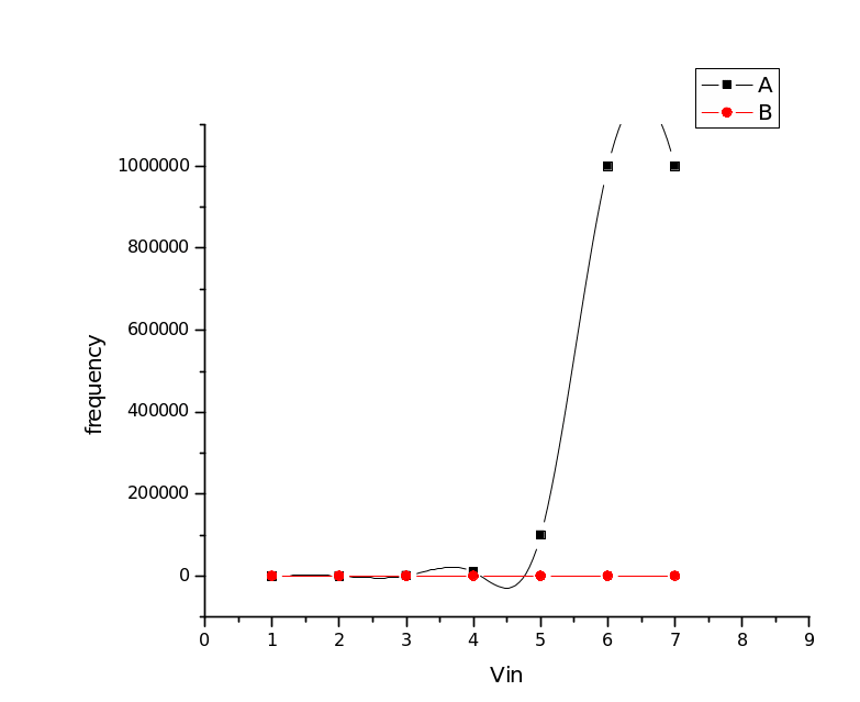
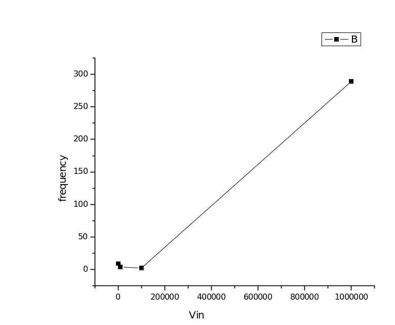
The graph for open voltage gain part A
Non-inverting Amplifier Part B
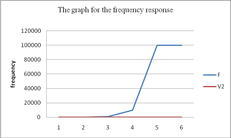
The graph for the frequency response
Voltage follower Part C
Inverting Amplifier Part D
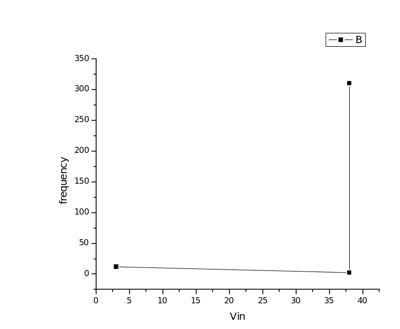
The graph for the inverting amplifier part D
Summer amplifier Part E
Measured results for summer amplifier part E
Deriving gains for inverting, non-inverting, and summing amplifier
In the case of the operational amplifier, the amplifier is in an open loop, which means that there are no connections that exist between input and output terminals in the above-given connection. In the open-loop connection, the operational amplifier acts as a gain amplifier, therefore giving three configurations that include:
Inverting amplifier
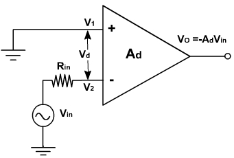
In this connection, the input is applied to the inverting terminal while grounding the non-inverting terminal.
Therefore:

So,

In the calculation of the gain for the amplifier, the negative sign shows that the output voltage is out of phase with the input by 180 °C, which in turn is amplified and inverted. This is as shown in the figure below:
The non-inverting amplifier
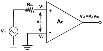
In calculating the gain in this connection, the input voltage is connected through the non-inverting terminal, while the connecting terminal is connected to the ground.
Therefore:


This means that the input is amplified by 

Summing amplifier
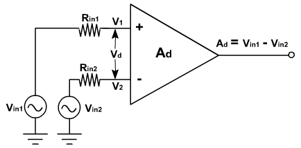
This connection involves the use of two inputs 


Therefore,


Results
Non-inverting amplifier
For the non-inverting amplifier, since it has a closed-loop,

Where:

and

Therefore, voltage gain,

Therefore,

For the given connection,


Voltage follower
For the voltage follower:

But


Therefore, gain

Inverting amplifier
For the inverting amplifier, the following connection is used
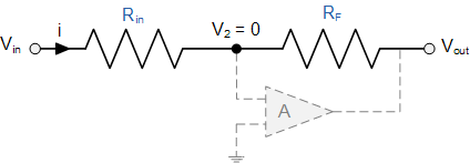
From the above connection,

Therefore,


Since

So,

Therefore, for a closed-loop,


Therefore,

The inverting summer
For the innervating summer,


Discussion
Usually, an open-loop connection does not have a feedback connection loop. Therefore, the operational gain is far much too high; hence, it cannot be useful in the operational amplifiers. To reduce this effect, some restrictions are necessary to ensure that the amplifier differential input is controllable through the slider in the circuit. From this assumption, if one attempts to make an output voltage test, the output will go beyond the required limits until it is reduced. Normally, when the open-loop slider is on the right, most amplifiers have a higher gain. Therefore, this assumption is null and so some restrictions should be in place to control the amplification.
Normally, for the operational amplifiers that are used to have one-pole-frequency, the gain at which the bandwidth is measured is nearly independent. Therefore, at this level, the gain-bandwidth product of the amplifier is equal to unity-gain, which is the gain of the amplifier within the amplifier. Usually, for an amplifier that has negative feedback, the gain is normally reduced to the open-loop bandwidth product given by the closed-loop of the amplifier. From the above analysis, it is clear that the frequencies of the parts A, B, C, D, and E have different relationships between the frequency f and voltages Vin and Vout.
Conclusion
Operational amplifiers have importance in the development of the building block of a number of electronic circuits. Some components that are involved in the operational amplifier are because of the external components that are related to the system characteristics. Some of these characteristics include the negative feedback, that is, gains are caused by external components that are interrelated to the system. An ideal operational amplifier should have the following properties; first, it should have an infinite loop gain. In addition, an op-amp should have infinite bandwidth to ensure that frequency magnitude is considered as flat everywhere. In addition, it should have zero input offset voltage to ensure that when the terminal is shorted, the positive equals the negative voltage.