CLIP is a process which constitutes the continuous liquid interface production technology, relies on a pool of resin that is fed into an oxygen-permeable window that has images that are projected into the printer with ultraviolet light to print solid objects using oxygen. The technique is used for printing solid objects instead of the time consuming traditional stepwise layer-by-layer printing method (Straub and Kerlin 6).
Here, the continuous generation method uses the monolithic polymeric technique as a key feature of the resolution technology often measuring below 100 micrometres enhances the printing speed. The printing technology is much faster than the traditional 3D printing techniques (Hudson 4). In addition, the products have superior mechanical properties compared with those that are produced using traditional 3D methods. Research has shown that the technique allows for the use of a wide range of raw polymeric materials that were originally not used in printing.
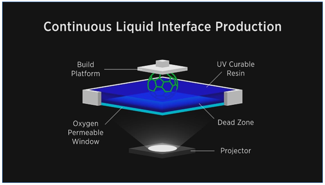
It is important to note that the printing technique can be optimised to produce excellent results by inhibiting the oxygen pathways. That is possible if an oxygen-permeable build window is prepared through a stereolithography process that enables the creation of oxygen containing dead zone. It has been established that the thickness of the dead zone is in the range of tens of micrometres, which calls for a judicious estimation of the correct parameters to be used as conceptualised in the simple architecture of the process in figure 2.
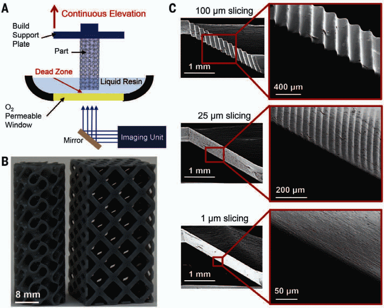
It is possible to achieve very high printing speeds because of the use of the CLIP technique as shown in figure 2. Here, the simultaneous elevation of the build which supports the pin causes an excellent increase in speed and better performance of the system based on the functionality of the high performance gyroid. However, making the dead zone thinner provides additional benefits of increasing the efficiency of the system in terms of speed and accuracy. That is achieved by use of good environment that allows for photopolymerization to occur effectively.
Metal Clay printing
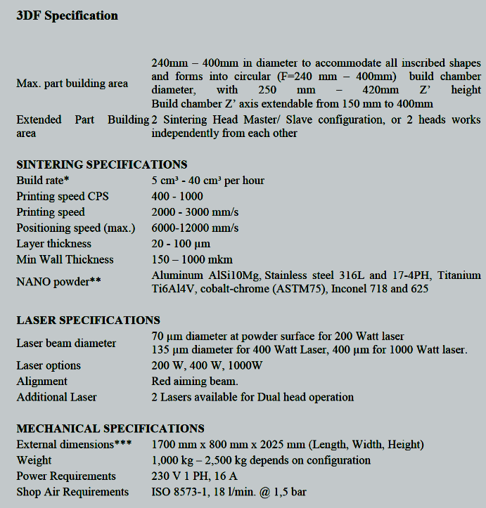
By use of direct metal laser sintering (DMLS) that uses a powdered metal bed upon which additive manufacturing is done, it is possible to do metal clay printing of a product. The process involves preparing the bed for printing on which lesser points are aimed at using the points that are defined in space on a 3D model. That allows for the melting or welding together of different points to create a solid in space (Gibson, Rosen and Stucker, 4). Figure 3 is a snapshot of some printer specifications.
3D Ceramics printing
Gibson, Rosen and Stucker note that the technique can be used to manufacture rapid prototypes of specific products (3). Prototyping can be done at room temperature by vulcanizing rubber mouldings to form different types of patterns on a solid body. However, several methods have been suggested that can be used for rapid prototyping among them being the selective inhibition sintering and the extrusion-based 3D printing techniques.
On the basis of empirical evidence, Hung, Tseng and Hsu argue that the techniques rely on the use of a composite ceramic-binder to shape the ceramic material before being subjected to the firing phase to remove the binder after which sintering is done to make the desired ceramic component (11). The production process consists of creating the power, shaping, green machining, de-binding, sintering, and machining the resulting object.
Printer design specifications
Several printers exist in the market and among them is the nano powder direct metal sintering system. The printer has been widely used in the manufacturing and medical fields with a lot of success. During the design processes, the customer needs and requirements are factored into the develop process using specialized designs that optimise the performance of the nano capabilities of the printer.
Speed
The printer speed is defined using different parameters such as the time required to print in the Z-direction especially for printers with a vertical build speed because in such cases, the printing situation is ideal and the loss of speed is not a dominant matter. Additional parameters that affect the printer’s speed include volumetric printing efficiency, the accuracy of the material used, and the type of material being used.
On the other hand, the print speed is a function of the parts resolution and the dead zone thickness of the assembled elements and the level of the resolution used in the printing (Chua and Yeong 3). For instance, it is possible for a dead zone thickness of 20 µm to reach a printing speed of 300 mm/hr.
Aperture nozzle
The speed can be adjusted for each specific printer, the job specifications, the desired level of accuracy, and the printing mechanism in use. For instance, the desired printing speed can be achieved by configuring the aperture of the nozzle. That is done by consolidating the metal powder using a localized microwave to do additive manufacturing of 3D structures for systems that have a resolution that is greater than 1-mm3.
On the other hand, the filament parameters can be used to configure the speed at which the printing job can be done. Other suggestions to improve the printing speed include using software configurations by changing the software parameters and fine tuning the position of the printer’s nozzle of the machine.
Suggestions by Martin, Bowden and Merrill point out that the speed can be improved by improving the quality of the material to be printed (3). The other suggestions include controlling the temperature of the surface’s planarity of the printing plate, enhancing the design and improving part orientation, and redesigning the mechanics of the printer. Reducing the size of the nozzle ((>=0.4 mm) leads to better quality work which is achieved at lower speeds. The diameter of the nozzle can also be made to vary between 0.2 and 0.8 mm for better results.
It is important to note that the cross sectional area of the nozzle affects the quality and speed of the print job. That is in context of the volumetric flow of printing material in the nozzle’s channel area. The nozzle’s diameter and printer speed specifications are illustrated in table 1. Results in table one are based on an experiment that was conducted by Chua and Yeong who concluded that speed depends on the nozzle diameter (3).
Sacrificing cost
The characteristics that are used to determine the price include the cost per cubic centimetre or cost per cubic inch and the specific part geometry and the accuracy of the printer.
Extrusion
Extruders come either in the integrated form or in the remote type of extruder. Extrusion using the integrated type is slower when compared with the remote type because it comes with bulky materials which cause a lot of friction, making the procedure less efficient (Martin, Bowden and Merrill 4). Dual extruder options provide of using two filaments instead of one, which enables the printing of dual colours to happen.
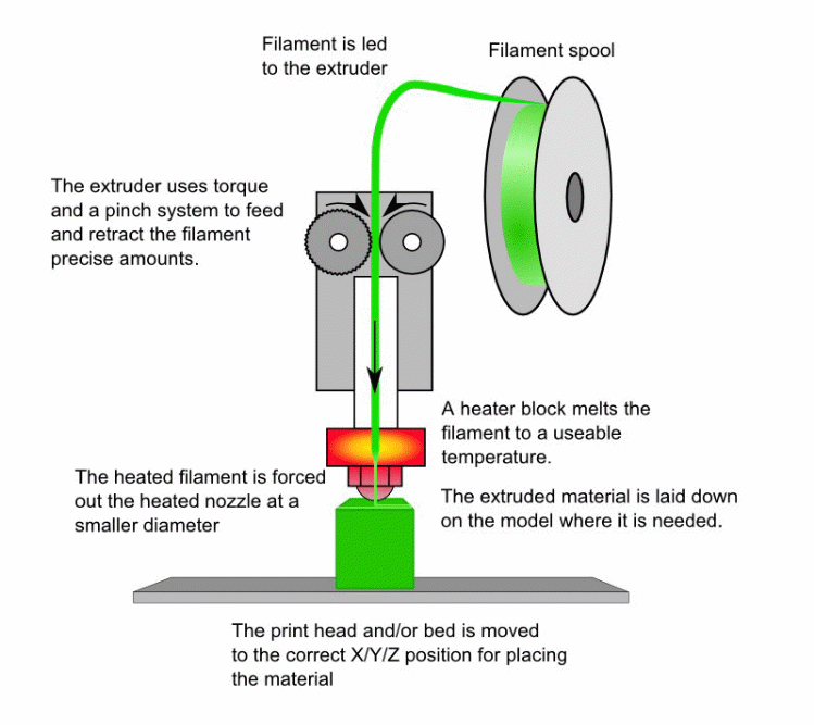
It is imperative to argue that remote extruder systems have the functional capability that enables the printing mechanism to push the printing filament through a hollow cable that has been inserted into the system to support the printing process. The rationale is to ensure that there is permanent feed for the hot end of the thermoplastic material.
The extrusion mechanism is shown figure 3 along with the components that have been used to assemble the product. It is evident that the process involves the extrusion of the thermoplastic material for the 3D printing to be done. Here, the material is first heated to melting point and then subjected to the extrusion process. The melted material is placed one layer on top of the other in a layering process that allows for the oozing of the plastic in order to allow it to form the desired shape. The extruder consists of various components that have been integrated together with different functions. Positioning of the extruder is shown besides the filament pool. The extruder uses the torque mechanism to perform its functions.
The extruder does not necessarily consist of the component that oozes out the molten material but it is the part that plays the significant role of feeding the hot end of the filament. It has been demonstrated in that extruders are the components that provide significant differences that exist among different types of printers.
Screw mechanism
The motion system of the 3D printer uses different types of screw mechanisms. Conversion of the linear motion of the system into rotary motion occurs through the screw mechanisms as movement happens between the screws and the nuts. It is important to ensure that the screw is kept rotating on the whole length of the nut. The lead angle can be sued to determine the amount of force that is applied on the mechanism. Keeping the lead angle of the screw low makes the design non-back-drivable because the axial forces applied on the nut are too low to turn the screw. It has been established that lead screws allow for positioning of heavy loads because of the large mechanical advantage associated with the screws.
The problem with lead screws is that they have large rotational inertia which limits the maximum speed of travel besides the large amount of heat they generate due to friction, making them inappropriate for use in situations that move frequently. However, sometimes ball screws are recommended for us instead of other designs to avoid the problem of the high amount of friction and backlashes that occur in the system.
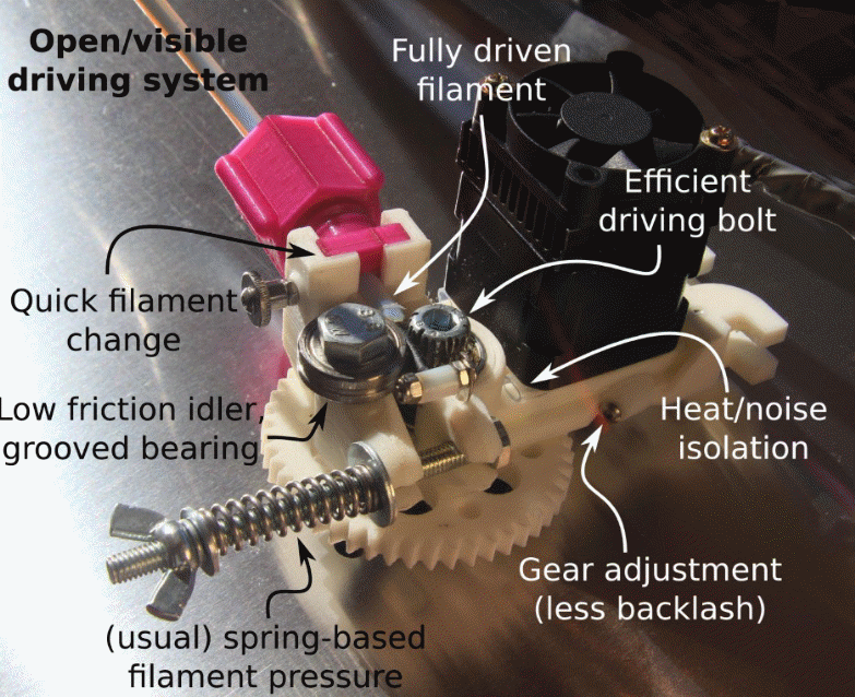
Examples include ACME lead screws on ball screws and threaded rods, lead screw systems, and ball screws. It is evident that the gear adjustment mechanism has been integrated into the screw mechanism as shown in figure 5 to address the backlash problem that occurs frequently in screw driven mechanisms.
Conclusion
In conclusion, the speed and quality of the printed products depend on a variety of factors such as the nozzle size, the temperature of the extruded material, and the printing mechanism among others.
Works Cited
Chua, Chee Kai, and Wai Yee Yeong. “Principles and Applications.” (2010). Print.
Gibson, Ian, David Rosen, and Brent Stucker. Additive manufacturing technologies: 3D printing, rapid prototyping, and direct digital manufacturing. Springer, 2014. Print.
Hudson, Scott E. “Printing teddy bears: a technique for 3D printing of soft interactive objects.” Proceedings of the SIGCHI Conference on Human Factors in Computing Systems. ACM, 2014. Print.
Hung, Kun‐Che, Ching‐Shiow Tseng, and Shan‐hui Hsu. “Synthesis and 3D Printing of Biodegradable Polyurethane Elastomer by a Water‐Based Process for Cartilage Tissue Engineering Applications.” Advanced healthcare materials 3.10 (2014): 1578- 1587. Print.
Martin, Robert L., Nicholas S. Bowden, and Chris Merrill. “3D Printing in Technology and Engineering Education.” Technology and engineering teacher 73.8 (2014): 30-35. Print.
Straub, Jeremy, and Scott Kerlin. “Development of a large, low-cost, instant 3D scanner.” Technologies 2.2 (2014): 76-95. Print.