The process of ramming a combination of aggregates, such as gravel, sand, silt, and clay, into formwork to make walls is known as rammed earth construction. The formwork is removed after the ground has dried to show solid monolithic walls. Rammed earth is a kind of construction material that is often utilized by numerous civilizations. It is made by compacting certain soils. Rammed earth, the most durable of earthen construction materials, may be used to create building blocks or to construct whole walls layer-by-layer. The earth is rammed into a mould in the form of a box to create construction blocks.
Humans have used a variety of construction materials from the dawn of time, including stones, wood, clay, soil, bricks, concrete, steel, and glass, among others, which have changed as new technologies have emerged (Giuffrida et al., 2021). There is a need for sustainable construction technologies in today’s world because traditional building methods pose serious environmental hazards. Earth has been a tried-and-true natural building material for thousands of years and may be utilized for contemporary ecological architecture when combined with modern techniques. Rammed earth building creates a solid, long-lasting monolithic wall by actively compacting the subsoil.
The use of earth construction methods has increased recently in Iran, the United States, and across the Middle East and Europe (Ávila et al., 2020). The need for environmentally friendly development is what is behind this rise. Earth is used to build floors and roofs in addition to walls in many developing nations where the benefits of earth building are more generally recognized. Earthen structures are sustainable, affordable, environmentally benign, and energy efficient. Both stabilized soil and unstabilized may be used to produce rammed-earth structures.
The objective of the Project: This Project’s major goal is to examine the rammed earth’s stabilized and unstabilized soil’s mechanical properties. To expose and propose appropriate building material and contraction of rammed earth as a building material. The aim is to have a better understanding of the operation of rammed earth materials and how stabilization might improve it.
Question: The Project uses molasses and wood chips to evaluate how rammed earth behaves in stabilized and unstabilized soil.
Methodology: In order to achieve the objective of the Project, a laboratory test involved engineered soil mixed up with molasses and wood chips, testing the Soil classification, Soil compaction, and Shear strength (shear box test, compaction test). Four different types of dry soil (fraction below 0.425 mm) pats measuring 4 cm in diameter and 1 cm in thickness was used for the shear strength test. The test was carried out by adding molasses and wood chips to the soil to test the Soil classification, Soil compaction, and Shear strength.
Discussion of the Results: Because of their low shear strength and compactness, soils S1, S2, and S3 mostly consist of silt and fine sand in their fine fraction. The soil S4 has a moderate shear strength, which indicates that it contains more clay than the other three soils and is more compact. As a result, rammed earth made with this soil is expected to result in more cohesive material. All of the soils, with the exception of S4, have clay contents that are below or almost at the lower limit of the recommended ranges.
Literature Review
Numerous studies have been conducted on the usage of lime and cement, two traditional stabilizers. The techniques for stabilizing cement and lime are widely known, and several applications have attested to the effectiveness of these conventional stabilizers. However, nothing is known about the usage of non-traditional stabilizers such as molasses, wood chips, and sodium chloride (Raavi and Tripura, 2020). It is strongly advised that further research be done to ascertain the applicability of non-traditional soil stabilizers and their effectiveness in improving the engineering properties of soil. This review of the literature aims to determine the extent to which other researchers have investigated the engineering characteristics of soil stabilized using non-traditional stabilizers as relevant to this study.
Soil Classification
The American school of soil scientists uses a classification Soil Taxonomy, which is also widespread in other countries. Its characteristic feature is the profound elaboration of formal criteria for assigning soils to a particular taxon (Pidwirny, 2021). Soil names constructed from Latin and Greek roots are used. A particle size distribution is a list of values or a mathematical function that determines the relative number of particles present as a function of size. The Proctor compaction test is a laboratory method for determining the optimal index at which the soil becomes most dense and reaches its maximum dry density. Soil compaction is carried out for various moisture contents, and in each case, the dry density is determined. Furthermore, a plot of dry density versus moisture content is plotted, namely the densification curve.
Test procedure for the proctor compaction test:
- Weigh mould body plus base plate but not the extension collar.
- Place the mould with the collar attached on the floor. Half fill the mould with loose soil.
- Compact the soil by applying 27 blows of the rammer, uniformly distributed over the soil surface.
- After compaction of layer scrape surface of the soil. Place an equal layer of soil and compact with 27 blows as above. Repeat with a third layer which does not project more than 6mm into the collar above the mould body (if it does repeat compaction with less soil).
- Remove collar, cut away soil level with the top of the mould body. Replace any course material removed by pressing in finer material into the voids. Weigh mould body and soil.
- Repeat test on 5 separate soil samples each with different moisture contents.
Equations that will be used for this test:
- the bulk density (ρ) of each sample in Mg/m3
ρ = mass of wet soil / volume of mould
- the dry density (ρd) of each sample
ρd = ρ/1+w*Mg/m3
- plot the curves on the same graph corresponding to 0%, 5% and 10 % air voids

Gs = particle density in Mg/m3, (assumed equal to 2.65 or 2.70)
ρw = Density of water = 1 Mg/m3
Va = The volume of air voids in the soil, expressed as a percentage of the total volume of the soil (equal to 0%, 5%, 10% for the purpose of this experiment)
Stabilization of Soil
By modifying the natural soil qualities with an additive, soil stabilization is typically understood to mean substantially improving the engineering properties of soils. Other soils or materials such as Portland cement, lime, fly ash, asphalt cement, polymers, and fibers are examples of possible additives that can be used to improve soil stability (Meek et al., 2021). Soil is given strength with cement. In clay soils, lime is often used to regulate plasticity.
Purpose of Soil Stabilization
Soil stabilization serves three objectives. The first is strengthening it to increase its capacity to support the weight. The second objective is to reduce or eliminate dust that is produced when equipment and aircraft are operated in dry weather or arid areas by binding soil particles together. The third goal of soil waterproofing is to maintain the inherent or artificial strength of soil by obstructing the entrance of surface water (Gil-Martin et al., 2021). There are now a growing number of non-traditional additives being explored for soil stabilization. The main categories of non-traditional stabilizers include salts, acids, enzymes, molasses, wood chips, and other natural substances. Depending on the goal of the Project, the kind of in-place material, and the cost of the addition, using non-traditional additives may be economically beneficial.
Types of Rammed Earth
Rammed earth comes in two primary types: Raw, which is carefully mixed clay, sand, silt, and water, and stabilized, where some kind of binder, usual cement, is added to hold it together. Raw rammed earth is a preferred material for many architects. Earth is a mixture of clay and other natural minerals that may be used as construction materials without the need for firing (Raavi and Tripura, 2020). Due to the material’s low embodied energy and lack of firing, it is a sustainable substitute for conventional building and surface materials.
According to research, while developing raw earth solutions for interior surfaces, you may produce a variety of color possibilities by combining different clays from various regions. Additionally, there are methods already developed for combining other materials, including jute, wheat, hemp, and rice, to produce a variety of natural textures (Ávila et al., 2020). Using unprocessed earth as an interior surface has several advantages, including being natural, sustainable, strong, and lasting. This all-natural material may be used to finish the walls, making them feel almost like a second skin. It is ideal for many environments, including residential and commercial, indoor and outdoor settings.
A small quantity of cement is added to stabilize rammed earth in order to boost its strength and durability. Rammed earth walls that have been stabilized hardly ever require further protection, but to lengthen the material’s lifespan, it is often coated with an air-permeable material (Dabakuyo and Onchiri, 2022). A sustainable, low-energy construction method called cement stabilized rammed earth (CRSE) uses inorganic soil, often sourced from the construction site, with a tiny amount of Portland cement as a building ingredient.
What is Stabilized Rammed Earth
A combination of gravel, sand, silt and a trace quantity of clay are rammed into position between flat panels known as formwork to create rammed earth walls. For added strength and durability, stabilized rammed earth is mixed with a modest quantity of cement (Preciado and Santos, 2020). Rammed earth may be utilized for multistore load-bearing structures since it is highly strong in compression. Rammed earth is often quite resilient, but it has to be shielded from heavy rainfalls and prolonged moisture exposure.
Except in very exposed settings, the majority of contemporary Australian rammed earth walls do not need extra waterproofing. A sustainable, low-energy construction method called cement stabilized rammed earth (CRSE) uses inorganic soil, often sourced from the construction site, with a tiny amount of Portland cement as a building ingredient. Various parts of the globe are seeing an increase in demand for this technology since it will benefit construction experts.
Unstabilized Rammed Earth
Rammed soil that is “unstabilized” has no extra binder elements (such as cement or lime). Utilizing natural soil without additives lowers the embodied energy and increases the construction’s ability to be recycled. Unstabilized rammed earth is still used today as a construction material because it is affordable, recyclable, and environmentally beneficial (Loccarini, 2018). Its use in the past had been predicated on extensive empirical knowledge of the local resources. In several nations, normative documents have been created to enable the evaluation of rammed earth soils since this information was mostly lost or is no longer adequate.
Reason Why Unstabilized Is Better Than Stabilized Rammed Earth
Since most experts believe that stabilized earth building primarily refers to cement-stabilized earth construction, they are not at all in favour of promoting stabilized earth construction in urban housing ((Preciado and Santos, 2020)). Even though stabilized earth construction is less expensive than brick masonry, it is often more expensive than what the majority of the poor can afford. The expensive nature of stabilized rammed earth is what makes many people dislike it.
Despite the fact that stabilized earth is a low-energy alternative and could be cost-effective in many circumstances, its accessibility to rural and urban individuals who have low earnings is far from satisfying ((Loccarini, 2018). Additionally, it is unfortunate that many practitioners of systematic stabilization are unaware of or appreciative of a soil’s inherent qualities and begin stabilizing soil prematurely when it is not really necessary.
The Behaviour of Mechanical Materials Properties
Civil engineers need to be aware of the mechanical material properties of both stabilized and unstabilized rammed earth. Civil engineers are becoming more interested in unstabilized earthen construction because of its “green” attributes of little environmental effect and energy efficiency during the lifespan of construction. However, a number of significant disadvantages, such as relatively low strength and water penetration, prevent the use of earthen materials in traditional construction (Raavi and Tripura, 2020. The following are different parameters to characterize the mechanical behaviour of rammed earth.
Unconfined Compressive Strength
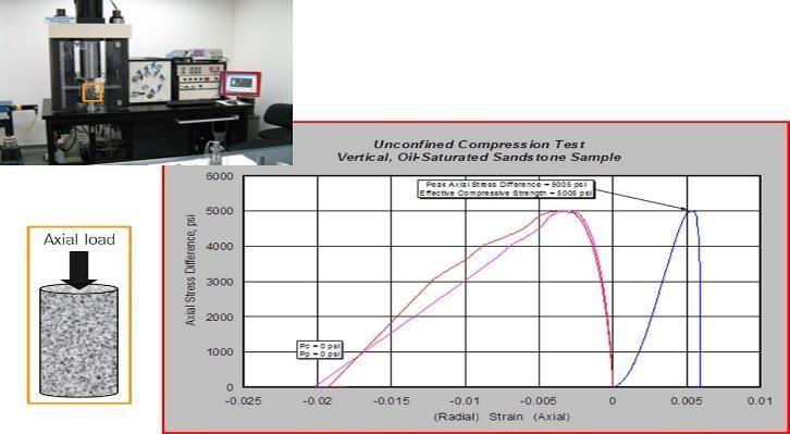
As is the case with the majority of brittle materials, the unconfined compressive strength (UCS) has traditionally been the primary parameter to describe the mechanical behaviour of RE (stabilized and unstabilized). Although far less discussed in the literature, additives meant to improve the tensile or flexural strength of RE have also been explored. It serves as a measure of a material’s durability (Raavi and Tripura, 2020). The greatest axial compressive stress that a right-cylindrical sample of material can sustain in an unconfined situation when the confining tension is zero is known as the unconfined compressive strength (UCS).
In order to determine the compressive strength, uniaxial compression tests are performed perpendicular to the direction of the earth strata, mostly on tiny cylindrical samples with a diameter that is twice as high as it is, but cubic specimens of various sizes have also been utilized. To really make the findings of the various research completely comparable, a uniform testing process for this content would be required (Raavi and Tripura, 2020). It uses the Unconfined Compression Test (UCT), a straightforward laboratory test procedure, as an example to evaluate the mechanical characteristics of rocks and fine-grained soils. It offers measurements of the rock or soil’s stress-strain properties and undrained strength.
Shear Strength
The capacity of a material to withstand forces that cause its internal structure to slide against one another is known as shear strength. Either the vertical or horizontal direction may be used to gauge a material’s shear strength. For instance, the material will show horizontal shear strength if the force causes the layers of the item to move in that direction (Raavi and Tripura, 2020). In contrast, the material will show vertical shear strength if the force causes the layers to move in that direction. Consider pushing on both of the extreme ends of a horizontal stack of books to raise them in order to better grasp shear strength (each hand acting as a support). Squeezing the stack of books creates a compressive force that creates a frictional force between the volumes. The books are prevented from collapsing and sliding apart by friction, a vertical force.
Shear Box Test
A shear box test is an essential method to determine necessary information about soil features. The shear box test is a testing method used to determine the shear strength of a soil sample (Raavi and Tripura, 2020). The soil is re-compacted inside a shear box, and the soil’s friction angle is then determined by direct shear, and the tests are carried out under saturated conditions.
Test Procedure:
- Using the two locating screws, connect the two halves of the shear box together.
- Place the porous stone plate into the shear box followed by the grid plate with the serrations at right angles to the direction of shear. Then carefully place the soil sample into the shear box. The second grid plate is placed on top of the soil and pushed gently into the sample. This is followed by the second porous plate and finally the loading pad.
- The jack is brought to bear up against the container at the bottom half of the shear box. To apply the normal load a transducer is set on top of the pressure pad and set to zero.
- The load is applied automatically by the machine by the use of weights. The rate of strain should be approximately 2% per min. The vertical displacement and the horizontal load are recorded at set intervals of horizontal displacement. These intervals are given on the data recording sheet at the back of this hand-out.
- After the test, the sample is removed from the shear box and inspected for voids, large stones, or other objects which may have unduly influenced the shearing strength. The final moisture content of the sample is then measured.
- The test is repeated on separate samples for a number of normal loadings, doubling the load for each test. At least three tests should be carried out.
Equations used for a shear box test:
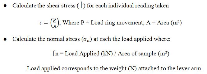
Solid things follow the same rules as intangible ones. Assume the horizontal or vertical force is larger than the material’s shear strength. The item may then encounter shear failure, which causes it to split into two or more sliding halves (Raavi and Tripura, 2020). For instance, if a force is given to an I-beam in a structure, it may shear or split into two pieces that collide with one another under vertical stress. Knowing the shear strength of materials is essential for the design of mechanical and structural devices, as well as the selection of materials to be utilized for application in the construction, automotive, aerospace, and other engineering sectors.
Bending Strength
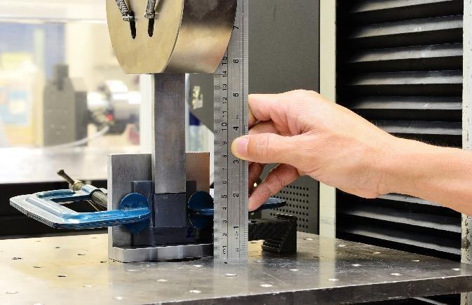
A material’s capacity to withstand deformation when under stress is referred to as its bending strength or flexural strength. Flexural strength is measured as the greatest attainable flexural stress value after a bending test as per ASTM D790. The load at yield, commonly calculated at 5% deformation/strain of the outer surface, is reported as the flexural strength or flexural yield strength for materials that considerably deform but do not break (Raavi and Tripura, 2020). At the concave surface, the test beam is under compressive stress, while at the convex surface, it is under tensile stress.
Bending Test
A bend test is a method for measuring stiffness and yield properties of certain materials. During the test, the values of the bending force and deflection are recorded. The three-point bending test gives the values of the modulus of elasticity (Raavi and Tripura, 2020). The material characteristics are then determined. The entire test sequence is shown in a stress-strain curve and can also be recorded with a video camera. Bending tests are performed to obtain information about the bending behaviour of the tested material from the single-axis bending stress. In case of brittle materials, the bending strength is determined this way. Dealing with ductile materials, the limit yield point, the greatest possible bending angle as well as Young’s modulus are determined, in case of an elastic deformation.
Test procedure:
- Ensure the mould is clean, free from dust and debris. Mould oil should be applied to all inner surfaces and the mould should be tightly assembled.
- Place the concrete in the mould in three equal layers. Compact each layer 175 times with the tamping bar. When the top layer has been tamped, trowel the top surface level with the top of the mould. Clean the sides and top lip of the mould.
- After 24 hours, loosen the nuts and bolts on the base and side of the mould and carefully remove the beam. Care must be taken as the cube is still soft.
- Mark each cube with a reference number. Place the beam in the curing tank for the required number of days.
- Clean the beam mould.
- Remove the beam from the curing tank, wipe clean the surfaces and ensure the bearing surfaces of the supporting and loading rollers are smooth and free of any projections.
- Record the length, width, thickness and weight of the cube.
- Place the beam in the flexural tester so that the upper trowelled face is vertical and facing the operator. Ensure the beam is placed centrally in the tester.
- The flexural tester then applies a constant load to the beam. The load shall be increased until the beam fails, and the maximum load applied to the beam shall be recorded. The appearance shall be noted. Clean up and dispose of all debris.
Equations that will be used for this test:
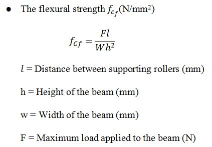
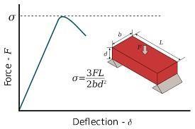
Three instances are shown in the image, which comes from ASTM.org. Material samples are often tested in a three-point bending configuration to quantify it, with the stress applied to the specimen cantered between the two supports. The maximum bending moment will be produced by this configuration in the specimen’s centre, which is not the best indicator of the material’s overall performance because greater flaws close to the support points won’t affect the recorded flexural strength (Raavi and Tripura, 2020). The curtain rod bending because of the weight of the curtain is an excellent illustration.
Construction may be improved using stabilization procedures. However, the soil has to satisfy a few characteristics if the objective is to get a fantastic mechanical performance (Avila and Gallego, 2019). Research shows that it is advisable to utilize soil with linear shrinkage lower than 11% in accordance with Australian Standards, sand content lower than 64%, and preferable fine particle concentrations between 21% and 35% for cement or lime stabilization (Asal, n.d.). The growth of RE’s strength is known to be significantly influenced by the moisture content present during manufacturing. Typically, a number that is somewhat near to the optimum moisture content (OMC), which permits the soil to have its maximum dry density for a given amount of compaction energy, is used.
Cube Test
Testing of concrete cubes for strength will make it possible to verify the quality of structures or concrete mixtures, as well as to identify defects in a timely manner. The compressive strength of the concrete cube test provides an idea about all the characteristics of concrete (The Constructor, 2022). By this single test one judge that whether Concreting has been done properly or not. Concrete compressive strength for general construction varies from 15 MPa (2200 psi) to 30 MPa (4400 psi) and higher in commercial and industrial structures (The Constructor, 2022). Compressive strength of concrete depends on many factors such as water-cement ratio, cement strength, quality of concrete material, quality control during the production of concrete, etc (The Constructor, 2022). Various standard codes recommend a concrete cylinder or concrete cube as the standard specimen for the test.
Test procedure:
- Ensure the mould is clean, free from dust and debris. Mould oil should be applied to all inner surfaces and the mould should be tightly assembled.
- Place the concrete in the mould in three equal layers. Compact each layer 35 times with the tamping bar. When the top layer has been tamped, trowel the top surface level with the top of the mould. Clean the sides and top lip of the mould.
- After 24 hours, loosen the nuts and bolts on the base and side of the mould and carefully remove the cube. Care must be taken as the cube is still soft.
- Mark each cube with a reference number. Place the cube in the curing tank for the required number of days.
- Clean the cube mould.
- Remove the cube from the curing tank, wipe clean the cube surfaces and ensure surfaces are smooth and free of any projections.
- Record the length, width, thickness and weight of the cube.
- Place the cube in the compression machine with the trowelled side facing to the side. Close the door and apply load until cube fails. Record the maximum load the cube failed at and work out the strength of the concrete.
- Remove the cube carefully. Examine the cube for type of failure and horizontal tensile cracks. Clean up and dispose of all debris.
Equations that will be used for this test:
- the compressive strength of the cube (N/mm2)
Moisture Content – Dry Density Relationship
In soil compaction, the main goal is to keep individual soil particles close together. This way, the dry density of the soil improves. The soil that has maximum dry density is suitable for various constructional purposes. However, the soil’s maximum dry density through compaction can be achieved only at a certain moisture content referred to as optimum moisture content (Kang, et al., 2022). Therefore, the compaction process purely depends on the relationship between the soil’s moisture content and its dry density.
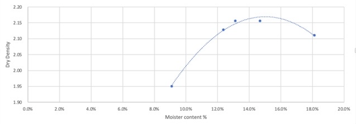
Generally, dry soil contains particles that do not interact with one another. In the case of attempting to compact this soil type without water, it becomes stiff, resulting in cracks and gaps formation. Meanwhile, the addition of water forms a thin film around each soil particle, helping them to successfully come into contact, making the soil denser under compaction. At a certain point in time, the air volume in the soil sample becomes minimum, whereas the dry density of the soil reaches maximum. This point is called the maximum dry density point; it indicates that further addition of water should be discontinued (Kang, et al., 2022). The moisture content associated with the soil’s maximum dry density is called “Optimum moisture content.” Consequently, if water is added above the optimum moisture content, it will occupy the extra space due to the absence of air volume, and dry density will reduce. The compaction curve below showcases the change in values of dry density with respect to soil’s water content.
Soil Moisture Content Test procedure:
- Weigh a clean dry dish to 0.01g (m1).
- Place soil sample in the dish and replace lid quickly.
- Weigh dish and contents to 0.01g (m2).
- Remove lid and place dish and contents in drying oven at 105° for 24 hours or in a microwave for 3 – 4 minutes until sample is fully dry indicated by no further loss in mass.
- Remove dish and quickly replace lid and allow dish to cool.
- Weigh dish and contents to 0 01g (m3).
- Dispose of contents and clean the dish.
The moisture content (w) can be calculated as a percentage of the dry soil mass using the equation:
Where:
- w = moisture content (%)
- m1 = mass of container (g)
- m2 = mass of container and wet sample (g)
- m3 = mass of container and dry sample (g)
The data for moisture content computation can be found in the following table:

In turn, the information regarding the sample density is illustrated in this table:

Judging by the grapth, the optimum moisture content is 14,7% corresponding to the dry density of 2,16 Mg/m3.
Ground Stabilization and Reinforcement
Ground Stabilization Using Molasses
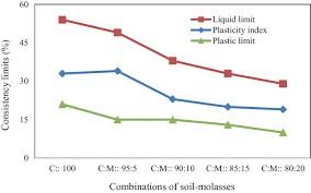
The most valuable by-product of the sugar business is molasses. In this study, blackstrap molasses—a by-product of raw sugar from sugarcane is the molasses being discussed. The last by-product of the third boiling cycle in the production of sugar is blackstrap molasses (Preciado and Santos, 2020). This kind of Molasses is exceptionally viscous and has a very dark colour. Products made from molasses bind the soil particles together like flimsy cement.
Molasses stabilization of expansive clay soil improved the California Bearing Ratio (CBR) readings and the soil’s capacity to support loads. Molasses may thus be used to stabilize expanding clay soil (Dabakuyo and Onchiri, 2022). Additionally, the expansive clay soil’s tendency to expand was controlled with molasses. It is evident that the influence and improvement on the permeability, cohesiveness, and internal angle of friction of soil after the addition of molasses during field stabilization have not been emphasized in laboratory studies by other researchers.
Ground Reinforcement Using Wood Chip
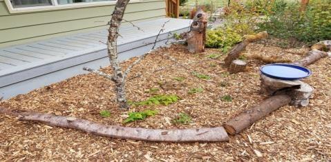
Poor shear strength, high compressibility, and low permeability are some of the unfavourable engineering characteristics that clay soils exhibit. If the properties are wet or subjected to other physical disturbances, they deteriorate much more. Soil reinforcement techniques are used to stabilize the soil prior to building. Wood chips are a biodegradable waste product that, after being recycled or reprocessed, may be used to reinforce soils. It has been discovered that adding wood chips to soils improves their strength characteristics (Gawriuczenkow and Wójcik, 2020). This material has samorphous silica, which indicates the presence of cementing properties that can develop good bonding between soil grains in case of weak soil.
A Case Study Rammed Earth in Western Australia.
This study explains the criteria and reasoning for choosing cement-stabilized rammed earth as a practical substitute for the typical typologies (mostly steel-framed buildings) in isolated parts of Australia. The suitability of the soil present in situ has been experimentally explored in order to overcome the restrictions caused by the absence of adequate Australian standards guidelines in the rammed-earth building (Meek et al., 2021). Studies have been done on the unconfined compressive strength of various soil types and cement contents.
According to the research, rammed earth building offers substantial benefits over the traditional steel-framed homes typically constructed on the Peninsula. Durability, thermal efficiency, affordability, structural integrity, and environmental sustainability were taken into account while evaluating the benefits (Strazzeri and Karrech, 2022). Due to the absence of explicit and thorough recommendations in Australian manuals and guidelines, experimental tests conducted in the laboratory of the University of Western Australia were used to establish the compatibility of the soil samples that were already accessible in situ. According to the study, the materials gathered on the Dampier Peninsula may be utilized to build rammed-earth structures. The use of 10% cement content guarantees that the necessary strength is provided, even in the event of flooding. The application of a silicone-based chemical admixture avoids moisture ingress in the event of near-horizontal rain.

Importance of This Thesis to Civil Engineers in the Future
The goal of the thesis is to modify the silt clay soil’s engineering qualities in order to make it acceptable for building small earth-fill dam embankment works. These engineering features include permeability, poor compaction, heaving, and viscous fluid behaviors when the soil is wet (Abhilash et al., 2020). The development of the environmentally friendly rammed earth building sector and the expansion of its application will be facilitated by greater technical knowledge of the material (not only in remote areas but also in metropolitan and rural areas). In accordance with the soil’s grading curve, the amount of clay present, and the type of clay particles present, studies are currently being conducted to determine the proper amount of cement and water to be used to obtain acceptable performances (not just in terms of strength, but also durability).
Knowing how soil behaves in terms of its mechanical qualities is crucial for civil engineers. It is necessary to evaluate the qualities of soil to see whether it may be utilized as a foundation or as a building material. Understanding and interpreting how soils will behave in the field depends heavily on the examination of fundamental engineering features of soils via laboratory testing. Khadka (2020, p.126) conclude that raw earth is used in earth-building methods to create walls; therefore, evaluating the soil is important since not all soils have the right qualities for earth construction.
The stability of civil engineering constructions is influenced by the geotechnical qualities of the soil, and most of these properties interact with one another. Around the globe, there are several types of soil with unique properties that are likely to have an impact on how well buildings are built with the soil work. Before employing any available soil for building, it is essential to determine its properties. Natural soil has a unique mix of sizes, and specific ratios of these sizes may be used as a useful construction material (Abhilash et al., 2020). This highlights the need to assess any soil before using it as filler or structural material in the building sector. The problem is that, given that not all soils are acceptable and that certain classes perform better depending on the approach used, a method of assessing them must be adopted.
Reference List
Abhilash, H. N. et al. (2020) ‘A novel experimental study to investigate the interface properties of rammed earth’, Construction Materials, 175(5), pp.1–9. Web.
Asal, A. (2021) Building with earth-sustainable stabilization and additive manufacturing for rammed earth construction. Bachelor thesis. HTWG Konstanz – University of Applied Sciences.
Ávila, F., Puertas, E. and Gallego, R. (2020) ‘Characterization of the mechanical and physical properties of unstabilized rammed earth: A review’, Construction and Building Materials, 270, p.121435. Web.
Dabakuyo, I. and Onchiri, R.O. (2022) ‘Mechanical properties of compressed earth block stabilized with sugarcane molasses and metakaolin-based geopolymer’, Civil Engineering Journal, 8(04), pp. 780-795. Web.
Gawriuczenkow, I. and Wójcik, E. (2020) ‘The effect of soil mineral composition on the compressive strength of cement-stabilized rammed earth’, Materials, 13(2), p.324. Web.
Gil-Martín, L.M., Fernández-Ruiz, M.A. and Hernández-Montes, E. (2022) ‘Mechanical characterization and elastic stiffness degradation of unstabilized rammed earth’, Journal of Building Engineering, 56, p.104805. Web.
Giuffrida et al. (2021) ‘Prototyping of a novel rammed earth technology’, Sustainability, 13(21), p.11948. Web.
Kang, Q. et al. (2022) ‘Study on the effect of moisture content and dry density on shear strength of silty clay based on direct shear test’, Advances in Civil Engineering, 2022. Web.
Khadka, B. (2020) ‘Rammed earth, as a sustainable and structurally safe green building: A housing solution in the era of global warming and climate change’, Asian Journal of Civil Engineering, 21(1), pp.119-136. Web.
Liu, Q. and Tong, L. (2017) ‘Engineering properties of unstabilized rammed earth with different clay contents’, Journal of the Wuhan University of Technology-Mater. Sci. Ed., 32(4), pp.914-920. Web.
Loccarini, F. (2018) The behaviour of rammed earth structures: Sustainable materials and strengthening techniques. PhD thesis. University of Braunschweig. Web.
Meek, A.H. et al. (2021) ‘Alternative stabilised rammed earth materials incorporating recycled waste and industrial by-products: A study of mechanical properties, flexure and bond strength’, Construction and Building Materials, 277, p.122303. Web.
Preciado, A. and Santos, J.C. (2020) ‘Rammed earth sustainability and durability in seismic areas as a building material’, IOP Conference Series: Earth and Environmental Science, 410(1), p. 012108.
Pidwirny, M. (2021) Soils and soil classification. Kelowna: Our Planet Earth Publishing.
Raavi, S. S. D. and Tripura, D. D. (2020) ‘Predicting and evaluating the engineering properties of unstabilized and cement-stabilized fibre-reinforced rammed earth blocks’ Construction and Building Materials, 262, p.120845. Web.
Strazzeri, V. and Karrech, A. (2022) ‘Energy and thermal performance of a typical rammed earth residential building in Western Australia’, Energy and Buildings, 260, p.111901. Web.
Alejandro, J. R. and Dermot, W. D. (2018) ‘Earthen buildings in Ireland’, in Wouters, I. et al. (eds.) Building Knowledge, Constructing Histories. Boca Raton: CRC Press, pp. 787-794.
‘Compressive strength of concrete – cube test’ (no date) The constructor. Web.