Abstract
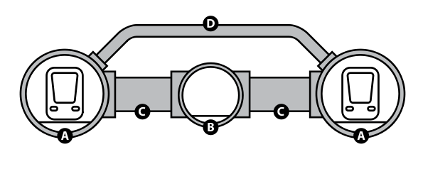
The report looks at key design principles with specific emphasis on how axial and transverse deformation forces behave on tunnels. The mathematical relationship between longitudinal and transverse wave vibrations in the design and construction of underground passageways is considered. Parameters considered in the design process include peak particle velocities and other forces due to seismic movements. Circular and rectangular designs are considered in this report with special emphasis on the technical aspects in addition to varying excavation methods which depend on ground conditions. The report focuses on channel tunnel as a case study. The channel tunnel consists of three tunnels interspersed with pipes at an interval of 375 meters with two rail tunnels separated by a distance of 30 meters between which a central pipe 4.8 m in diameter runs. Relief ducts 2 meters in diameter connect the tunnels in a sequence of 250 meters. Controlled louvers supply fresh air regulating air conditions in the tunnel. Tunnel boring equipments assembled at the site cut through the marble and chalk along the line of construction. The boring machines’ cutting heads consisted of spinning blades, upon which forces were applied to enable penetration into the soil and rock. The rock and slurry were mixed to form a conveyable mucky product in the drilling and cutting process.
Aims
The aims of this project included:
- Looking at the practical use of skills and techniques in underground tunnel design and construction by undertaking a study on channel tunnel as a case study.
- Identifying the type of engineering equipments used in tunnel design and construction in different grounds.
- How surveys are conducted for a proposed site for tunnel construction
- The most important aspects of tunnel design and construction
Objectives
The objectives included:
- Conduct an investigation into the principles and techniques of tunnel design and construction.
- Identify specific engineering and design requirements for a rectangular and circular tunnel.
- Identify specific deformational and compression forces acting on circular and rectangular tunnels.
- Determine the techniques of analyzing soil and rock samples.
- Identify the behavior of engineering component under different operating conditions.
- Determine specific areas of future research
Definition of Terms
Deformation: A change in shape caused by external or internal forces acting on a body.
Ground particle velocities: These are three dimensional particle displacements induced by vibrations due to earth movements. This depends on successive rate of arrival of waves.
Force: That which causes an accelerating effect on a machine or an engineering component to cause a desired effect.
Young’s Modulus – This is a quantitative measure of a material’s stiffness. It is a ratio between the tensile and compression forces.
Modulus of Elasticity – It is the ratio between the stress and strain of a rock or any solid material.
Tunnel – An underground passageway constructed through rock or soil that can accommodate traffic moving from one point to another.
Tensile strength – This is the resistance of a material to tensional forces acting on it. It provides a value which determines the maximum amount of force a material can be subjected to without deformation.
Faults: A geological discontinuity that occurs in a rock mass resulting from tectonic earth movements.
Poisson’s ratio: This is a ration defining the stretch and compression effects on a body due to perpendicular forces and to axial forces in the direction of the force.
TBM: Tunnel Boring Machine used to cut through different types of rocks and strata. Different types of tunnel boring machines are used for with different designs
Introduction
Tunnels are underground passage ways dug in different types of rocks. Formidable challenges face engineers in the design and construction of such tunnels. These range from the appropriate use of technology to conducting underground research on the types of rocks and soils. Tensile and compression deformation forces and seismic activities in the proposed line of construction are important factors to consider in the survey and design process.
Background
The engineering project is a 50.5 km long undersea rail tunnel commonly referred to as the “Chunnel tunnel” connecting northern France and the United Kingdom. This complex structure is a display of engineering genius that took many years of survey, data collection, analysis in addition to other studies culminating in the design and construction of the tunnel. The tunnel is constructed through a geological line composed of chalk and clay. The chalk and clay layers include gray chalk, chalk marl, glauconitic and gault clay. It is a complex structure 7.6 meters in diameter with a 4.8 meters central service tunnel with a wide gestation time. Shafts from both ends of the tunnel provide ventilation and cooling system. A minimum vertical gap between both tracks in a monolithic reinforced concrete provides provision for track layout and flexible loading conditions on both ends. In 1973, a was treaty signed by the French president and British prime minister for the construction of the channel but construction did not start until later on. Tunnel boring machines some quite large were used in the boring process. Engineers faced challenges particularly with standing time for soft walls, collapsing walls, faults along the line of construction, different languages for tunnel workers, and other geological problems. But the construction of channel tunnel was a successful engineering project.
Key Concepts
Geostatic forces presented formidable challenges in tunnel design and construction for engineers working on channel tunnel. Key design concepts included an investigation into the axis of orientation of the tunnel, cross sectional size, shape, spacing between excavations, and an analysis of rock mass volume. Unit mass of soft and hard earth materials, lateral loads or forces caused by the earth’s vibrations, horizontal movements due to tectonic pressures and loads that exert stresses on tunnel were considered. Specific parameters for a design model before excavation started included a measure of the unit weight of earth (y), the modulus of elasticity (E), Cohesion (c), Friction angle (ø), Poisson’s ratio (v). These measurements provided data on specific properties for material to be used in excavation process.
Seismically induced forces due to earth vibrations and other stresses such as man-induced stresses are described by Price and Freit (2009) as virgin induced which act both vertical and horizontal. Vertical stress is due to weight overburden and horizontal stress is due to seismic tectonic movements. The average horizontal stress (K) is given by this expression:
- K= Sn/Sv, where Sn are average horizontal forces acting on a tunnel.
Stress measurements are taken to determine stress fields. According to Price and Freit (2009) carrying out stress measurements involves using varying loads on a stress measuring instrument by stressing the original earth load to different sizes until the original volume of the earth load is achieved. The loading and unloading procedures help determine the tensile strength of a rock. Axial and transverse displacements of the soil due to seismic activities and their direction of propagation are key concepts considered. In addition, engineers considered both circular and rectangular tunnel designs by conducting a detailed analysis of effective wave propagation of the earth movement, the peak ground particle velocities, and peak ground particle acceleration according to the article on (Channel tunnel 23).
However, engineers were faced with the important challenge of determining wave propagation velocities and accelerations in the soil. Theoretical and actual values differed widely. This discrepancy was traced to the problem related to the soil’s compatibility.
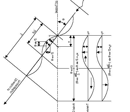
- q= angle of incidence
- r= Radius of curvature
- Vs and Vr are the peak particle velocities
- Cs and Cr Effective propagation velocities
- As and Ar are Peak particle accelerations
In the design process emax = ±Vs/2Cs±AsR/C²s cos3q
The above formula is useful for calculating the curvature component under seismic forces. The tunnel design was based on key concepts of wave types and the mathematical relationships between longitudinal waves and curvatures deformations. Specific parameters for calculating sinusoidal thrust along a tunnel’s axis include the shear force with a wavelength-L, amplitude due to displacement D, and an angle of q wave type. On this basis, the forces due to wave motions with the potential to cause destruction on a tunnel due to earthquakes can be determined. The graph below illustrates the behavior of the forces (Channel tunnel 40)
Types of Tunnel Design
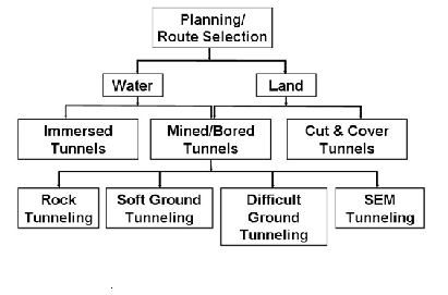
This analysis narrows down to two design types. Channel tunnel construction was to overcome a specific problem or obstacle. These obstacles included water, a mountain, etc. Since tunnels provide a safer, faster and more efficient form of transportation, their design is an engineering challenge. Engineers must plan well by conducting a geological analysis of the ground to look at the risks involved. An analysis of the construction materials is done and the construction is based on developed plan. According to the findings two types of designs were compared. These included:
- A Circular design and
- A Rectangular design
In addition forces acting on rectangular and circular tunnels were considered in the design. According to the engineers conducting the analysis, a circular tunnel could experience an ovaling deformation on a shear wave front and a racking deformation on a tunnel with a rectangular cross-sectional area as illustrated below.
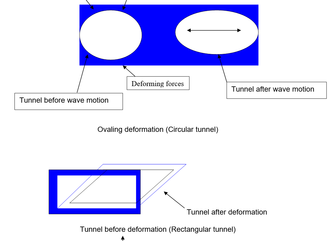
Appropriate data was obtained based on tests and analysis conducted on these design models. Rectangular tunnels have the disadvantage of space utilization compared to circular tunnels (Channel Tunnel 45).
Design Procedure for Tunnel Construction
The procedure for designing a tunnel for construction is based on data collected after identifying the necessary alignments, functional requirements, conducting a geotechnical analysis and various technical aspects of tunnel design in hard and soft rocks besides conducting an analysis of the forces due to earth loads, the design criteria, cultural and environmental issues, conducting a feasibility study and risk analysis, and documenting all the necessary available data. This was followed by an analysis of available construction methods and tools and evaluation of the best alternatives. According to the The institute of civil engineers (1993), other factors considered included the drainage system for the tunnel and lining requirements. Safety measures, ventilation requirements, and lighting requirements were incorporated in the design. Gradually of importance were the maintenance procedures for the tunnel. A tunnel must remain serviceable once it has been commissioned for use.
Specific procedures included determining the soils, rocks, and other parametric considerations including the Q-value of rock mass, span or height, spacing of bolts, and the thickness of shotcrete (Zhao, Shirlaw & Krishman 2000, p. 300). According to Zhao, Shirlaw and Krishman (2000), Q-value mass constitutes the quality of the rock mass under consideration, while other requirements fall under a rock’s support sub-system. The support of these rocks is solidly based on five principles among them being a matrix coding component based on the cause effect component, an expert system which explains cause, effect, and results (Zhao, Shirlaw & Krishman 2000). The final equilibrium to be established a dynamic simulating component fed into a Hopfield network in tunnel design is factored with a database (Zhao, Shirlaw & Krishman, 2000, p. 310).
Once all these information is in place, Zhao, Shirlaw and Krishman (2000) assert that the initial rock tunnel design can be conducted by analyzing and determining reinforcement measures for the tunnel, assessing the current design and making improvements, considering the behavior of the design in a variety of rock conditions. The interaction intensity can be monitored, and an assessment of the degree of the rock’s safety before commencing construction determined (Zhao, Shirlaw & Krishman 2000). In addition to these, a thorough analysis of the rock’s tensile strength and other rock properties should be conducted. In conducting a seismic analysis, two methods were considered. These included the ordinary seismic analysis and the Geotomography analysis.
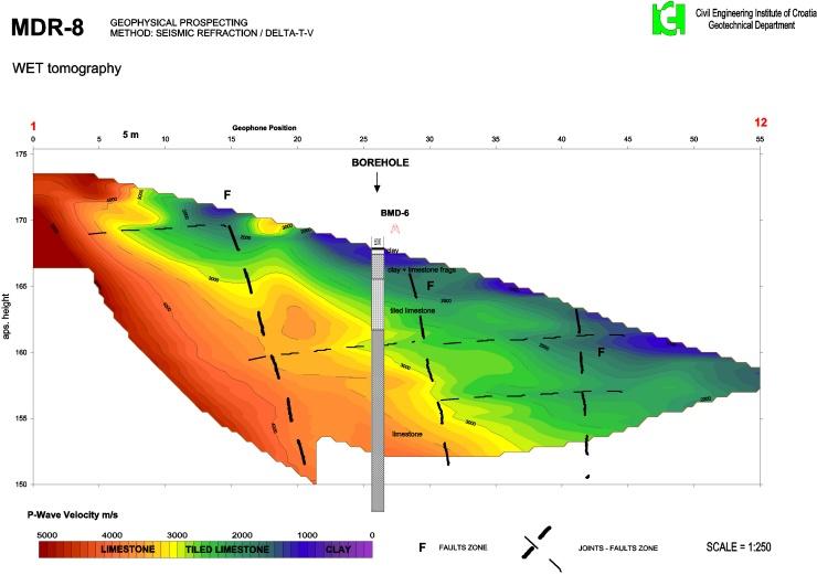
Boring revealed the type of underground rocks. These led to the classification of rocks and seismic velocities. The ordinary seismic analysis revealed five velocity layers, which appeared to be parallel or lateral to the ground taking a convex shape. Data from seismic geotomography revealed seven layers with a boundary line of 3.2 km/sec a concave curvature. The study revealed a 3 complicated seismic 2.5 km/sec layer. Field reconnaissance also revealed some fresh outcrops of rocks (Zhao, Shirlaw & Krishman 2000).
Zhao, Shirlaw and Krishman (2000) have provided a detailed account of the type of tests conducted to determine the kind of earth movements the channel tunnel could be subjected to.
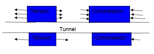
According to Channel tunnel designers, two types of deformations considered were axial and curvature types. Axial deformation, according to RUNNING LINE TUNNEL DESIGN (n.d) consisted of compression and tension forces acting on the tunnel.
Tunnel Construction Methods
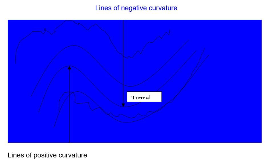
Illustrates a Curvature deformation along a tunnel
Landscape topology determines the construction method used. The cut and cover method is a simple method for shallow tunnels mostly used in subway construction. A trench is excavated and roofed over. This method includes processes such as the conventional method in which a trench is excavated on the ground then covered with a load carrying support placed for supporting the covering material. Another term for the bottom up method is the caisson method. Here a drilling rig is used to insert walls on bedrock although soil is excavated a little distance ahead of a tunnel. Tunnel walls are then constructed from the foundation. Slab is laid on the floor after which side walls are erected. Once construction is complete, the subway roof is put in place. Different construction materials may be used for this including corrugated steel. Another method is the top down method. A trench on which the concrete wall is erected is prepared using a trench cutter. The slurry wall acts as a barrier to water seepage into the tunnel. The slurry wall is clay like mixture that laterally exerts hydraulic pressure to counter balance forces against the tunnel during excavation preventing it from collapsing. Bentonite and water form the raw products for the slurry. This stabilizes the excavation process by reversing the permeability of the tunnel’s soil.
The slurry can then be recycled and replaced with concrete after tunneling is completed. Castings are prepared using a form that takes the actual shape of the trench, and then the cast is waited to cure before it is removed. The subway is then restored after the after the trench has been filled.
The cut and cover method is significantly applicable in less congested areas and forms an inexpensive option to other methods of construction. The ground condition determines the technique used in the cut and cover methods.
Pipe-jacking
Specially made pipes are pushed into the soil using hydraulic jacks designed for the purpose. When working with this method, forces acting on the pipes, the ground, and the walls must be analyzed and manufacture recommendations for the equipments used on varying load conditions followed strictly. The loading process must factor the thrust and anchorage loads, kind of load transfers, and the interjacks. In the process, regular checks should be the routine with specific and cautious alignments of the equipments. Shield loads and total loads should be ascertained before commencing the work.
This method emphasizes on the use of mud slurry to stabilize the ground. In addition thrust estimates indicate that the muddy slurry plays a vital role in the pushing procedures. The significant benefit of this method is that it can be used in non disruptive constructions in overcrowded areas to mitigate problems associated with traffic and other forms of congestion. Pipes are pushed through bores made underground by a special machine referred to as drivage machine. Force is used to push and apply the thrusts necessary to penetrate the ground ahead of jacks. In more modern times, the use of circular pipes has been replaced with rectangular pipes. This has the advantage of efficient use of space.
Full faced
In this method excavation is done in a combination. That implies that it is a single operation. Rolling cutters mounted on a tunnel boring machine (TBM) apply thrust with a high speed spinning head on the tunnel crushing any rocks on them. Perforation of the workforce in the drilling process extends up to 5 meters in depth of the drilling holes. Weakness zones are handled better with blasting and use of conventional drilling techniques. This method reduces ground displacements significantly. Tests done when using this technique include centrifugal modeling to determine effects of roof support and the effects of displacements while drilling.
Blasting
Another excavation method is blasting. This method is appropriate for hard rocks. This technique is an engineering tool that depends on the stability of a rock, and incorporates studies on rock fragmentation when an explosive charge has been detonated on it. Bedding planes and a rock’s tensile strength determine the amount of force required to cause sheer displacement within a rock. Gas pressure causes rock fragmentation during detonation assisted by dynamic stress from the explosion. It is important to determine particle flight velocity and trajectory during an explosion to avert risks associated with such an explosion. Interlocking within a rock can be drastically reduced in a detonation and this reduces as the depth of a rock increases.
It is important to control blasting damages resulting from detonations to significantly produce a clean pre-smoothing of walls in a tunnel. The technique combines a simultaneous detonation procedure with very closely arranged detonations. This technique creates a clean surface with minimized risks particularly of a rock’s structural stability. Indications show that underground blasting causes reduced impact on rock fracture being less than half a meter in depth. A normal blast and a pre-site blasting method produce different results and the pre-site blasting method seems to be of an advantage in tunnel construction. A detonation must be precisely designed to achieve optimal results. A wedge is used to create a void into which a blasted rock displaces itself on detonation. This involves carefully drilled holes charged with detonations set off with regular delays.
Blasting must be appropriately designed and controlled to reduce blasting damage. This calls for efficient communication on the part of those involved.
Fire setting
The surface of a hard rock of a tunnel wall is heated to a certain temperature then water is poured on it making it crack due to rapid expansion and contraction due to the cooling effect. Scaffolds are used for safe and risk free use of explosives. This process is repeatedly done for the overall tunnel length.
Top heading and bench method
This method involves the construction of a smaller tunnel known as a top heading on the crown of the tunnel top. Two methods provide the initial opening according to (Tatiya, 2005). These include a single heading and double heading methods. Tatiya (2005) describes the single permanent lining for the roof erected after a calotte has been driven in when the top head has been driven into place. The lining walls are finally constructed though it takes time for them to set. Excavation resumes once a gap has been created through which excavators can proceed with their work. This excavation takes place below the excavation head. This level is referred to as the bench. The excavation proceeds from either sides or faces of the tunnel. (Tatiya 2005, p. 300) asserts that the second method consists of top heading and bottom heading. Both headings are driven concurrently followed by work on calotte and roof lining done gradually. Muck can be handled independently using this method. The top of the tunnel may consist of rocky soil or soft rock. Tatiya (2005) concludes that this method has the significant advantage in which it allows engineers to determine rock and wall stability as work progresses. This method allows tunneling to be done from both ends of the tunnel particularly when the tunnel is long and passes undersea. For enlargement purposes, the top part is used and this method has wide acceptance and use.

Potential Problems in Tunnel Design
Engineers face formidable challenges and constraints in tunnel design and construction. According to Tatiya (2005) these range from surrounding structures such as buildings, bridges, and other structures that may be affected by the construction procedures. Lateral forces due to tectonic movements of the earth, earthquakes and other strong vibrations majorly due to inertia of land masses. Large displacements of the ground and ground failures due to weaknesses in structural form, lateral forces, vertical forces, pressure vaults, and severe ruptures present another problem on these tunnels. Soil may mix with water to make a muddy mixture in the face of seismic vibrations forming a combined force that could crush a tunnel. In addition severe ground shaking may thoroughly damage a tunnel.
Racking of tunnels is another potential problem. Seismic forces may cause displacements leading to severe damages particularly for transportation systems such as roads or rail links running underground. Challenges and problems exist for tunnel construction in hard and soft rocks. Soft grounds may include clay and sand. Gravel, mud, and silt constitute soft grounds. The stand up time for this ground is short and engineering requirements dictate the use of a shield to avoid cave-inns. This steel structure is thrust into the ground. This structure creates a perfectly circular penetration on the soft ground in the construction process allowing workers to position precast concrete linings as they remove debris as a result of tunneling.
Other problems which may result from land forces include deformations such as axial, ovaling, curvature, and racking deformations for circular tunnels. When an oblique seismic force is applied on a tunnel, a curvature deformation may form on a tunnel in a linear or lateral direction. This horizontal deformation is also common with an axial deformation. A look at ovaling deformations, ground stability, ground conditions, and faulting provides a clear view on the effect of such problems on the design and construction of tunnels among others.
Ovaling deformation
Ovaling deformation also referred to as racking deformation results when the direction of wave movement is vertical, oblique, or lateral to the tunnel’s axis. This may cause a distortion or deformation of the tunnel lining when considering it from its end elevation. These deformations may act on a circular or rectangular tunnel. On both tunnels, the seismic force is predominantly due to the earth’s load and any designer must be critical when designing a tunnel based on these facts. The earth load’s factors’ predominance in this design over oval forces is partly due to:
- Earth or ground movements in the vertical direction which causes less thrust on a tunnel compared to lateral movements which cause severe distortions. These movements account for only 1/3 or 2/3 of the horizontal movements. Shear forces in the vertical direction cause horizontal movements or vibrations. For overriding rocks, the vertical thrusts may be more drastic than horizontal ones in magnitude. These localized vibrations attenuate quickly from the point of origin.
- An amplified propagation is possible for tunnels embedded in soft ground thus making vibrations more vigorously lateral. These wave propagations in the horizontal direction causes severe pull and push strains on rocks below a tunnel. In the design process, it has been proven that the resulting figures vary widely from those calculations based on soft ground compared to hard surfaces.
- Ground stability. Soil can easily liquefy thus easily prone to landslides.
- Faults may adversely damage a tunnel including tectonic movements in the lateral and vertical directions.
- Ground conditions such as stiffness or overall strength in overcoming forces or thrusts due to earth load may vary drastically.
Ground stability
When designing a tunnel it’s worthwhile to consider the ground stabilization elements by incorporating design features and measures to curb drainages, reinforcements, and the manner in which earth load is retained. Soils provide real challenges in its removal and replacement. An unstable ground may present problems that may even stall a tunnel’s construction.
Faults
These may present design challenges if the possibility of avoiding them in the construction process is nil. To accommodate them a design scheme should be provided with appropriate materials to withstand dynamic and static loads due to faulting movements. In addition to that, the actual location of a fault should be identified and the design fault displacement determined. These certainties drastically reduce associated costs. When stresses on specific materials are stronger than the ability to withstand those stresses, a fault occurs.
Ground conditions
Ground changes is due to factors such as the ductility and rigidity of connections, tunnel junctions, ventilations at the end connections of a tunnel, the drastic variation in stiffness of different land masses a tunnel crosses, local restraints of tunnel movements, and flexible and movable joints on tunnels. Contrasting movements apply varying loads on a tunnel when subjected to these varied conditions. Differential data obtained as a result of calculations done on these movements determine the kind of joints to design for a tunnel.
Engineering equipments
According to () eleven boring machines dug through the tunnel characterized by chalk marl from either sides of the tunnel terminals at cheriton and Coquelles. The tunnel boring equipments consisted of tunnel boring machines through various soil and rock types. Tunnel boring machines (TBM) are designed to bore through hard and soft rocks besides boring through sand. Harris (1996) asserts that the machines are designed to cause minimal disturbance to the surrounding grounds and ensue walls’ stability. The resulting tunnel is smooth in nature with minimum distortions to the surrounding walls. Challenges such as lining and walls’ stabilities are minimized in the process, a vital element in the use of these machines. Though TBM’s are difficulty to construct and transport, they are also very expensive to construct.
Basically a TBM machine is designed with a fast rotating head on which is mounted a cutting head that crushes ground as drilling advances. The machine cuts a wall when supported by hydraulic jacks which provide the required thrust. Different TBM’s are used on different geological grounds. TBM’s are designed for both soft and hard rocks. Two types of TBM’s are used for hard rocks. These include the open type boring machine which is supported during the drilling process with rocks chewed from the cutterhead. A gripper provides support for advancing in the drilling process. The forward thrust depends on the gripper’s shoes acting against the walls. Boring takes place in intervals. At the end of a drilling interval, referred to as a stroke, the gripper assembly is prepared for the next interval of drilling by relaxing and repositioning the gripper’s rear legs by extending them to start drilling again.
Site investigation
With limited geological knowledge at the time the channel tunnel was proposed, years of investigations revealed a valuable body of knowledge that guided the tunnel’s design and construction. Significantly seismic profiling from data on off-shore and land geological surveys was conducted to determine geological strata along the construction line. Off shore geological surveys included the sea floor of Dover straights. This is a 60 meter long deep sea bed of strait consisting of synclines and anticlines with basement outcrops at various points such as that at Marquise. The UK strait is of undisturbed less deformed basin than the French side.
Chalk forms part of the tunnel rising and dipping at varying degrees with an emerging flat sea bed. The structural geology of the tunnel was based on tectonic sedimentation at various points with varying thickness of chalk. There is rich evidence of compression and tensional effects along the line with deformations occurring at different points. The data provided evidence of seismic movements along the tunnel line.
A survey of the tunnel line indicated joints at different points varying in dip with joints and disjoints witnessed along the line. Other major challenges encountered during construction included regional ground water, minor acqiclide at the UK side and slab failures in the construction process.
Requirements for construction purposes were determined. Site investigation provided vital data for determining the cost and engineering equipments to use. According to Harris (1996) a site investigation and geological survey was conducted to identify the rock types and determine other geological factors for the construction process.
According to Harris (1996) the tunnel site had been investigated close to 170 years. This lead-in time clearly illustrates the intensity and exhaustive nature of the investigation. Harris (1996) indicates that more than 100 holes had been sank to conduct underground investigations despite the close to half a million pounds cost for each hole sunk along the tunnel line or close to it.
Chalk forms part of the tunnel which rises and dips at different levels. The channel tunnel line consisted of seronian chalks, flint, turonian chalk, cenomanian chalk with varying thickness with low permeability and water flow in the direction of fissures.
Some of the investigations conducted included ground motion hazard analysis. According to the Technical Manual for Design and Construction of Road Tunnels – Civil Elements In this analysis (2009, p.1) “The process by which design ground motion parameters are established for a seismic analysis is termed the seismic hazard analysis”. This analysis according to the manual was conducted to determine the projections of seismic points capable of causing severe movements in the site of the tunnel, determine the strength of the seismic point or source, and identify how intense and strong the ground design could be. The geographic location of the tunnel was determined which provided information on the depths of the faults characteristics of the seismic source. The ground movements vary in intensity. It was determined that the motion intensity be identified based on varying complexity rating. These included, existing hazard analysis, deterministic hazard level analysis, and ground motion parameters.
Existing hazard analysis
This analysis provides information on spectral acceleration values depending on site locations, earthquake levels, and other developments. This depends on available and published information.
Deterministic hazard level analysis
According to the Technical Manual for Design and Construction of Road Tunnels – Civil Elements (2009), maximum values assigned to seismic sources are used for each point or source then the design earthquake is evaluated form calculations based on the vibration intensity to determine the level of damage that can be caused by the seismic shaking. To carry out this study, a seismologist must identify the location of the fault formation, determine the attenuation level in relation to ground motion parameters, the behavior of the earth load in the motion in relation to source and distances involved, and identify the sources of the seismic motions based on the seismic motion hazard. This method is valuable for cases that have damaging effects (worst case analysis).
Other analyses conducted include probabilistic analysis approaches where highest and lowest values of seismic forces are identified, the magnitude of the earth’s movements, and then a probabilistic value determined. This value provides information on the strength of a seismic source movement.
Ground motion parameter
These parameters are important in determining the peak ground velocities and displacements to analyze the potential damages that can be caused by earth displacements. PGA can be used to determine attenuation due to ground movements. According to the Technical Manual for Design and Construction of Road Tunnels – Civil _Elements (2009), the following formula can be used in design process as there is a strong correlation of strong motion data:
- PGA = 0.394×10²(raise this to power 0.434c)
- Where c= 4.82+2.16log S1=.0013[2.3logS1+2.93]2
Geological mapping
The channel tunnel as a case study provided useful information on the geological map to determine and enumerate the requirements in design and construction. According to the findings, it had been established that the ground contained no major fault along the line of construction. According to Price and Freitas (2009), the geological survey clearly indicated continuous rock strata on both sides of the proposed site. Sedimentation created a deposit of strata made of Gray chalk, Chalk marl, Glauconitic, and Gault Clay. Chalk marl was identified to form a 25-30 meter layer with a percentage of clay in the range of 30-40%, with glauconitic marl impressed between chalk and gault clay in this sedimentation process. The percentage in content of clay prevents ground water from seeping into the tunnel in the construction process. A slight variation is noted in the English side. The dip varies from 5 degrees in the English side to 20 degrees in the French side. Faults and joints with varying magnitude are in both sides of the tunnel.
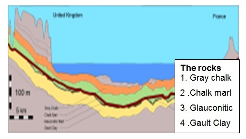
To accurately determine the profile various costly bores were sunk at regular hard clay, thus making it brittle and more likely to be fractured. Harris (1996) the survey did not reveal any intervals to determine the nature of the rocks and soils in the site and other geological aspects. Harris (1996) repots that the both sides had faults though they were minor, they could not impede the commencement of the construction process. Faults varied in size in the range of two meters. The faults from both sides were identified to contain a clay substance known as pyrite that contained calcite and was limited in size. Harris (1996) noted that microfossil assemblage provided a clear distinction in determining and differentiating the types of clay. A study conducted on both coasts was able to determine that the French coast had more geological hazards to impede the commencement of tunnel construction. It was determined to be ideal to locate the English terminal at Castle Hill landslip. Buttressing provided stabilizing elements when drainage adits were inserted
Rock testing
Phases to conduct rock measurement surveys for channel tunnel were took place on both sides of channel tunnel. According to Harris (1996), the methodology had experienced successive developments and was finally accepted in 1988. It consisted of a geophysical survey 1.5 kilometers within the tunnel’s alignment and separated by a distance of 800 m. Calibrations were done on the Geophysical Survey Microfix and Syledis navigation systems before being installed. According to Harris (1996), these provided a 3.12 range of accuracy on shorts at close intervals. Results indicated well functioning systems. A large amount of data was collected and made available for use.
The machines’ abilities to cut through rocks could determine the kind of machines used in boring. This could help engineers ensue maximum utility and productivity. The engineers collected a variety of soils and rocks and subjected them to geotechnical laboratory analysis with definite testing procedures. The physical properties tested in the soil and rock samples included, density, unconfined comprehensive properties on a 600 KN machine, the tensile strength of the soil and rock on a Brazilian scaled machine, static elastic modulus, and modulus of deformation. The modulus of elasticity (E) is calculated using the linear part of the curvature of a deformation (illustrated above), which depends on the maximum deformations and peak forces on the curvature of the deformation. Plasticity of a rock or soil is determined using young’s modulus of elasticity and the modulus of deformation. The ratio of the maximum deformation value to the specimen’s primary length is calculated to determine the value of fracture deformation.
According to Singh and Goel (1999), the tensile strength and compressive strength of a rock are determined to identify the actual roughness of a rock or soil sample. This behavior is measured on a scale which indicates relative toughness. A value of 9 on the scale indicates tough behavior, while in the range of 9 and 15 is an average value and a scale of 15 indicates brittle properties. Further soil and rock properties include normal tensile strengths and parallel bedding planes. This description is based on the ability of a machine to cut through rock or a rock’s cut ability. The calculated ratio varies from one upwards.
Another test is the Schmidt rebound hammer. This test provides data on the strength required cause rebounds. The higher the strength of a rock the lower the value obtained. This test is particularly suitable for those rocks with higher values of hardness. The test procedure follows a ten times knock on the test hammer and the properties of the resulting crater measured.
Other tests conducted on rocks included:
- Index tests. These tests are for determining rock cut ability which determines how well a machine will work in cutting specific rocks. It helps identify the best machines to use in the cutting processes. The basic reasons for these tests depend on differing values of shear strengths and the modulus of elasticity which determines plastic properties of a rock. Load applications on a test sample yield different values based on the cutting speed of a cutting head similar to that yielded on a cutter head. In the cutting process, the experience of the person handling the machine, the homogeneity of a rock, longitudinal and transverse inclination of the cutting head and rough profiling determine the cutting results. The relationship, the cutting rate (L), motor power (N), and the depth of cut or penetration (S) are represented by the equation: L= 0.075. S. N. Once the correlation coefficient has been determined, forces such as uniaxial compressive strength are determined.
- The abrasive value of a rock is another property to test. This relies on the coefficient of wear. Using a polarizing microscope, the coefficient is determined along the following lines. Mineral or rock concentrations which may include substances such as carbonates, silicates, polymeric mineral grains, Mica, among others. The coefficient of wear is then calculated based on this formula: F= (V*d*t)/100 where V is the proportion of other minerals expressed as a percentage, d is the diameter of the test particle, and is the tensile strength of the test sample on the Mpa scale.
- Other tests include the intensity of bonds within a rock and between rocks, rock homogeneity, solidification factors, and metamorphic transformations.
Stress Measurement Surveys
According to Amadei and Stephansson (1997), a number of methods were used to conduct rock measurement surveys. Indirect methods provided a means for determining stress in a rock’s body. Amadei and Stephansson (1997) clearly contend that measuring a rock’s stress is near impossible and this property can only be deduced for the whole rock body. The seismologists used six independent methods in analyzing the rock’s behavior. These included hydraulic methods which constitute hydraulic fracturing, the relief method which incorporates surface relief methods, underscoring, overcoring, and relief of large rock volumes. According to Stephansson (), other methods included the jacking method which constitutes the flat jack method, strain recovery method consisting of inelastic strain recovery, differential strain curve analysis, and the borehole breakout method.
From the above discussion it was noted that 100 bores had been sank along and some besides the tunnel trajectory. To determine the ground properties of the rocks where bores had been sunk different methods already mentioned above were used. One such method was the hydraulic method.
Hydraulic method
Amadei and Stephansson (1997), discusses this method as a composition of the fracturing method, sleeve fracturing, hydraulic fracturing and hydraulic testing on pre-existing fractures (Amadei & Stephansson 1997 ). Vertical and horizontal stresses play the principal role in determining the amount of stress that a rock can withstand. Vertical stresses are due to the earth load. This crack occurs due to a thrust by water on the rock that causes the rock to crack and tele-viewers provide information on vertical and horizontal fractures. Pressure time record is used to determine the horizontal stress components.
Some of the most well known tunnels
These include the Thames tunnel build under the Thames River, the Frejus tunnel under mount Frejus, the Seikan tunnel which happens to be the longest tunnel in the world connecting Hokkado and Honshu in Japan, and the Hoosac tunnel under mount Hoosac among many others.
Future Plans
Design and construction of underground tunnels is an engineering challenge that requires engineers to conduct detailed research on various aspects. In addition this requires a detailed body of knowledge, analytical data and detailed study and analysis of available information on tunnel design and construction. The above report majorly looks at the theoretical technical aspects and principles and their application on practical field on the topic. Of importance therefore is to look at design and roofing of tunnels as an important component in tunnel support. In addition to the study of the properties of materials used for roof support, the plan could incorporate aspects of cost and cost effective production of modern materials for roofing.
Detailed Research
From the above discussion, the researcher will concentrate in identifying cost effective modern engineering materials for tunnel roofing. In essence, the research will cover engineering properties of roofing materials, types of roofing materials including the cost of production of those materials using modern methods of materials technologies.
Research Topic
Each phase of tunnel design and construction constitutes wall supporting requirements as a dominant factor too ensue safety in the face of seismic vibrations, and other underground conditions. Engineers must consider the appropriate use of support as a measure of safety for the users of the tunnel. Typically, the properties of the materials particularly their strengths, installation and cost are of paramount importance. Therefore the research topic could be “Tunnel Roofing Materials”.
Conclusion
Tunnel design and construction is a challenging undertaking in the civil engineering field. Basic considerations on design and construction of these tunnels provide formidable challenges to overcome. Engineers must conduct detailed surveys and critical analysis of available and obtained data, conduct tests on the mechanical properties of soft and hard rocks to determine engineering requirements in the design and construction process. Seismic movements, wave motions and pressure due to earth loads, particle velocities and accelerations of underground soils and rocks due to deformation forces forms a fundamental part in analyzing a tunnel’s stability and construction methods. However, there is need to adapt modern cost effective engineering methods, material testing techniques, and adopt less costly methods and materials in tunnel construction. In addition there is need to conduct further research on roofing materials and identify the best and less costly modern materials for roofing tunnels.
References
Amadei, B., Stephansson, O., 1997. Rock stress and its measurement. Web.
Harris, C.S., 1996. Engineering geology of the Channel Tunnel [online]. Web.
Price, G. P., Freitas, de M., 2009. Engineering geology: principles and practice [online]. Web.
RUNNING LINE TUNNEL DESIGN, n.d. [online]. Web.
Singh, B., & Goel, R.K., 1999. Rock Mass Classification: A Practical Approach in Civil Engineering [online]. Web.
Tatiya R. R., 2005. Surface and underground excavations: methods, techniques and equipment [online]. Web.
Technical Manual for Design and Construction of Road Tunnels – Civil Elements , viewed, (n.d). [Online]. Web.
The institute of civil engineers, 1993. The channel tunnel: Terminal, part 2 [online]. Web.
Zhao,J., Shirlaw, JN, Krishnan, R., 2000. Tunnels and underground structures: proceedings of the International [online]. Web.
