Executive Summary
Since time immemorial, people have been exposed to several catastrophes such as flooding of rivers, lakes and other water bodies. Besides damage to their property, several people have lost their lives and loved ones in such occurrences. Governments have also incurred losses every year in efforts to save and relocate flood victims. In response to this, engineers developed ways of controlling floods to avoid losses incurred during the flooding seasons (Duchemin, 2009). This led to the creation of dams that would help to store and control the flow of water along existing water bodies. Later on, the discovery of hydroelectric power increased the need for developing larger dams that would control floods, generate power, as well as provide water for irrigation purposes.
As such, the objective of this study is to increase knowledge on the several techniques used in the construction of dams and their associated benefits. In this report, three dams namely; Hoover Dam, Three Gorges Dam, and the Snowy Mountains Scheme have been analyzed. In the first section, the construction techniques used in the construction of the dams and their hydropower stations are given in detail. The second section gives a brief discussion on the comparison of techniques used in the dams’ construction. Lastly, the third section gives a conclusive report of the key findings of the research.
Hoover Dam Construction
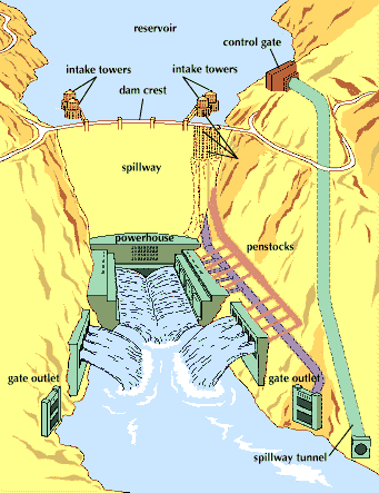
Hoover Dam is a concrete arch-gravity dam constructed in the Black Canyon of the Colorado River (Stevenes, 1988). Construction of the dam started in 1931 on the US and Nevada border and was completed four years later. President Franklin Roosevelt commissioned the opening of the dam in September 30, 1935, during the Great Depression. According to the Bureau of Reclamation (2006) the facility was put up to provide power, farm water and regulate river flow. The dam was built by Six Companies, Inc. which completed the works 24 months ahead of schedule. Hoover Dam is comprised of several features as indicated in figure 1 below (Barber, 2010).
River Diversion – Diversion Tunnels
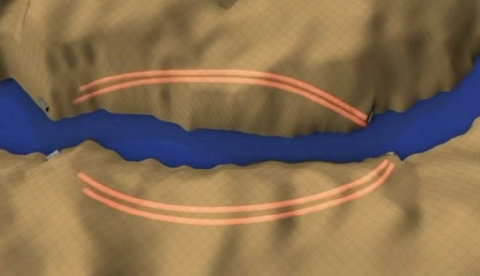
For the construction of the dam to commence, Colorado River had to be redirected from the building site (Dunar & McBride, 2001). As shown in figure 2, diversion tunnels were constructed within the river banks towards the lower end of the site. Each tunnel was 17 meters in diameter, two on the Nevada and the other two on the Arizona side. All the tunnels combined, added up to an approximate length of 5 kilometers (Hiltzik, 2010). Tunneling was conducted through digging, blasting and removal of accumulated debris over a period of 13 months.
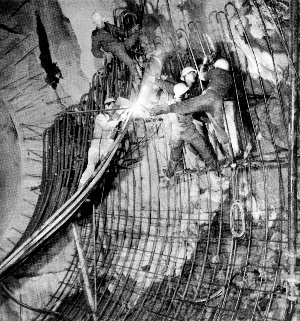
As tunneling progressed, the tunnel walls were covered in concrete linings with tunnel bases being poured first. Concreting the bases was done through the aid of gantry cranes, where after, mobile steel members assisted in concreting the sides (Barber, 2010). Lastly, pneumatic guns were employed in finishing the tops (Barber, 2010). On completion, the linings were thick enough to reduce the total diameter of the excavation by 2 meters. By blasting the protective cofferdam to the Arizona tunnels and blocking the natural course of the river using rubble, the water was diverted into the Arizona tunnels. However, Nevada tunnels were put in reservation for high water. After completion of the dam, massive concrete blocks were used to block the tunnels; therefore, leaving the lower parts to serve as the main bodies of the spill ways.
Construction of Cofferdams
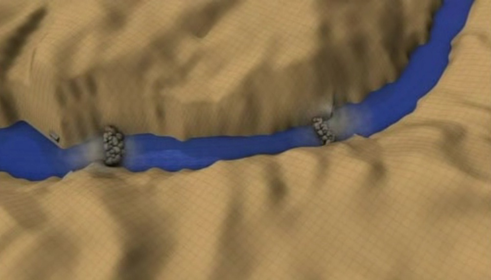
To speed up the diversion process, 2 cofferdams were built across the river channel. The cofferdams (figure 4) prevented river flooding into the dam site where several men were at work. The cofferdams were 29 meters high and 230 meters thick at the bases and comprised of 500,000 cubic meters of material (Allen, 1983). Workers used several trucks to create the cofferdams by depositing earth, debris and rocks into the river at the rate of four trucks per minute.
Excavations started after the immediate completion of the cofferdams. River clay and other accumulated deposits were dug out to reach a stable foundation rock (Allen, 1983). Since the canyon’s side-walls would bear the force exerted by the created dam (arch-gravity), construction workers [suspended on ropes] excavated the sidewalls too. These workers were referred to as high-scalers, and they removed loose rock using jackhammers and dynamite. Several holes were dug through the established foundation rock and refilled to increase its stability (True & Kirby, 2009). This helped to reinforce the dam’s underlying rock foundation. As such, grouting was done to allow for rock stabilization, and limit upward (uplift) pressure resulting from water seepage beneath the dam itself (Dunar & McBride, 2001).
Spillway Construction
Spillways were built to eliminate the problems associated with dam overflow. According to Dunar and McBride (2001) the spillways exist behind the dam but lie parallel to the river edges. Each of the two spillways is comprised of 30 meters long and 4.9 meters high fabricated steel gates. These gates are either remotely or manually operated depending on the volume of water present. The excess water falls several meters into the spillway tunnels where it is redirected into the main river channel.
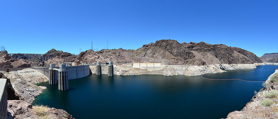
After the spillway lining was damaged (1941), a retouch with special concrete was done and surfaces were made mirror smooth (Hiltzik, 2010). However, the same damage occurred during the 1983 floods, necessitating the use of aerators.
Concrete Works
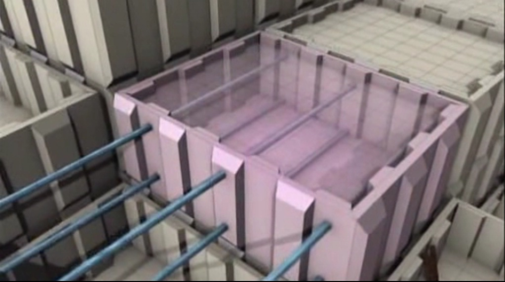
Concreting works started in 1933 when the first batch was used in the dam’s columns (Dunar & McBride, 2001). Uneven cooling of concrete may result in serious structural problems such as development of cracks and even structural failure. This is a possible scenario where large concrete works are undertaken, for example, in the construction of Hoover dam. In such a case, the resultant forces would lead to the formation of cracks within the dam’s body. As such, engineers at Hoover Dam avoided that possibility of uneven cooling by using interlocking blocks that were cooled by cold water through several steel pipes (figure 6). On cooling of the blocks, the steel pipes were filled with grout, as well as, the grooved spaces between columns (Allen, 1983).
To facilitate the pouring of concrete, a network of cables and pulleys was designed to help in the movement of building materials within the dam site. Huge steel buckets, with dimensions roughly 21 meters all around, we’re used to delivering concrete to the dam site. The buckets were controlled through a series of suspended cables that helped to move them towards the required location. In the construction, a total of 2,480,000 cubic meters of concrete and 937 kilometers of cooling pipes were used.
Hydro Station Construction
Location
The powerhouse excavation was done concurrently with the excavation for the dam’s foundation. The structure was located strategically towards the lower end of Hoover Dam (Dunar & McBride, 2001).
Construction
Concrete, steel, and rock material were used to make the 1,100 mm thick fully secure powerhouse roofing. Furthermore, layers of sand and tar were added to the roof (True & Kirby, 2009). Power generation started in 1936 when the reservoir had gathered enough water to sustain the generation of electricity. The power plant houses a total of 15 large generators and 2 small generators.
Construction Problems
Deaths, Extreme temperatures
In total, 112 deaths occurred during the construction period of Hoover Dam. Most deceased workers met their death from falling objects coming from loose rock and debris off the canyon’s wall. The temperatures were also extreme reaching levels of up to 49 degrees Celsius, and up to 60 degrees Celsius within diversion tunnels. These extreme working conditions resulted in difficulties and reduced the efficiency of the workers. Also, carbon monoxide poisoning led to approximately 42 deaths and was caused by the use of gasoline powered vehicles within the diversion tunnels.
Hoovers Heat of Hydration
Generation of heat during setting of concrete posed a considerable risk as the uneven cooling and contraction of mass concrete would lead to development of cracks and crumbling. To counteract these effects, engineers on the site established a technique of using several interlocking blocks rather than using mass concrete (Dunar & McBride, 2001). The blocks were massive and required cooling to facilitate the setting process. Therefore, the problem was subdued by forcing ice-cold water into the interlocking blocks via a series of steel pipes.
Accessibility Challenges
Accessibility to the canyon (dam site) posed a serious challenge to the workforce as no roads were leading to the site (Stevenes, 1988). As a result, both men and equipment had to come to the site on boats.
Three Gorges Dam Construction
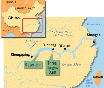
The Three Gorges Dam was constructed on the Yangtze River, under the project called ‘Yangtze River Three Gorges Project (TGP)’ (Veeck, Ponnell, Smith, & Huang, 2007). It is located at the Sandouping of Yichang city (Figure 7) and is the largest hydropower complex in the world (Power Technology, 2011). The main purpose of its construction was to enable flood control, generate power and provide navigation capabilities (McGill University, 2001). The Three Gorges Dam is constructed as a concrete gravity dam with its crest at 185 meters and highest height of 181 meters (Power Technology, 2011). The maximum annual power generation is 84,700,000,000KW/h. The detailed construction of the dam, its power plant and the problems encountered during construction are discussed in the following pages.
- Stage 1: (1993-1997): As described by River Closure, this stage took five years to be completed. It involved the preparation for commencement of the construction works (Veeck et. al., 2007).
- Stage 2: (1998-2003): As shown by the initial storage of water and power generation, the stage took a total of six years to complete (Veeck et. al., 2007).
- Stage 3: (2004-2009): This stage was completed in 2010, when power generation started in all the installed generating units (Figure 8).

Construction Technology Employed
River Closure Technology
During construction of the dam, CGGC successfully implemented the river closure of Yangtze River (Deyong, 2006). Three river closures were used to allow the conduction of hydraulic model tests, intensive calculations and research analysis on river closure. Finally, the technical difficulties in river closure and deep water cofferdam construction were overcome. New construction techniques and machinery such as the high pressure screw were used in erecting the cofferdam. Stage 2 cofferdams protected the main body works so effectively that the company was awarded the first prize of National Scientific and Technical Improvement.
Construction Technique of RCC Cofferdam of large size
The third phase cofferdam was a vast, temporary, but crucial structure in the construction of the Three Gorges Dam. Thin layer monolithic concrete pouring, interlayer pouring, continuous lift, and whole lift of formwork strengthened the concrete works (Deyong, 2006). During the construction of the 580 meters long cofferdam, these construction techniques increased productivity, and a concrete rise of up to 27.8 meters per month was attained.
High Intensity Concrete Placement Technology
Since the concrete used for construction of the TGP dam was massive (16,000,000 cubic meters), new technologies, workmanship and construction materials had to be used to have successful concreting. As such, the concrete pouring for the spillway section, left and right bank power plant section, and non-overflow dam section was contracted and constructed (Deyong, 2006). Examples of new technologies used in the construction include; high efficiency dehydrating agents; reinforcement steel cutting technique; and the use of computer monitoring system. These modernized techniques enabled the achievement of massive concreting at the site. During 1999-2001, the successive annual concreting level reached 4,000,000 cubic meters surpassing the rates achieved in the Itaipu (Brazil) hydropower project.
Technology for Temperature Control and Crack Prevention of Mass Concrete
During the construction of the Dam, temperature control was crucial to prevent the development of cracks in the cooling concrete. The temperature in the region reaches unusually high levels in summer, while the structure was gigantic requiring intensive pouring of mass concrete. Several temperature control measures were used, for example, selection of materials, and optimization of the concrete mix. Furthermore, triple pre-alarming systems for temperature control were used to monitor temperature control of concrete, intermittent period of concrete formed area, and for construction in special temperature (Deyong, 2006).
Blasting Technique
During the main construction works, smooth-blasting technique was used to cut reserved layers from rock mass (Deyong, 2006). This was made possible by creating blast holes poured on the outline of the excavation. During the temporary ship lock construction, the application of smooth-blasting technique helped to maintain stability in the vertical slope of the ship lock. Furthermore, new blasting technique such as production of immense power emulsion explosive at site, mixing carriage for explosive transportation, and network of the I-kon were used. These alone had an explosive load of 191.3 ton and effectively dismantled the concrete cofferdam averaging 186,700 cubic meters.
Heavy equipment represented by Tower Cranes
Tower Cranes are gigantic equipments employed in the construction of dams. They are used for pouring concrete, vertical transportation and concrete feed of raw mix. Tower Cranes were heavily used during construction of Three Gorges Dam, to enable the creation of a continuous supply and high intensity (Deyong, 2006). For instance, six sets of Tower Cranes were used in phase 2 of the dam’s construction.
Fabrication and Installation Technology of large-Sized Metal Work
In the Three Gorges Project, completed metal fabrications for the spillway and other dam’s sections amounted to a total of 9,100 tons. Automatic welding in full position technology was used in the fabrication of the metal parts (Deyong, 2006). The “flipchip” construction method was adopted during the installation of high pressure gate and gate groove. Additionally, welding challenges experienced during the installation of gigantic steel liners were reduced by the adoption of steel-bonded metal welding technique. As such, the application of these techniques enabled the successful realization in the mass application of stainless steel bonded metal in domestic hydroelectric area.
Construction Problems
Technological Challenges
Construction of the Three Gorges Dam was characterized by the use of concrete in large quantities with high construction intensity that resulted in construction challenges (Williams, 2009). For instance, 28,000,000 cubic meters of concrete had to be laid, and various techniques devised. As mentioned earlier, various techniques and technologies were used to counteract these technological challenges.
Snowy Mountains Scheme Construction
The Snowy Mountains Scheme was constructed to collect, regulate and use the waters for generating power to serve the southern parts of Australia (Commonwealth of Australia, 1950). Furthermore, it was established to supplement the Murray and Murrumbidgee Rivers that serve the fertile irrigation zone (Gale, 1999). This was possible because of sufficient water from snow and rainfall in the catchment area of the scheme. It took 25 years to complete the construction of the dam that comprises of 16 dams, 7 power stations, a pumping station, 145 kilometers of tunnels, and 80 kilometers of aqueducts (Snowy Mountains Hydro-Electric Authority, n.d.). The descriptions of the main dam construction, the hydroelectric power plant, and the problems encountered during construction are given in the following paragraphs.
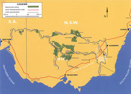
The overall design was completed in 25 years and comprises of the following features (Commonwealth of Australia, 1950):
- 16 dams.
- 7 power stations.
- 145 kilometers of tunnels.
- 80 kilometers of aqueducts and access roads were cut through the mountainous region.
At the scheme, there are five principal types of dams depending on the materials used in constructing their walls (Commonwealth of Australia, 1950). These are listed below.
- Rock-fill Dams.
- Earth-fill Dams.
- Concrete Gravity Dams.
- Concrete Arch Dams.
- Slab and Buttress Dams.
Eucumbene Dam Construction

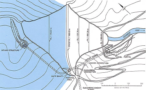
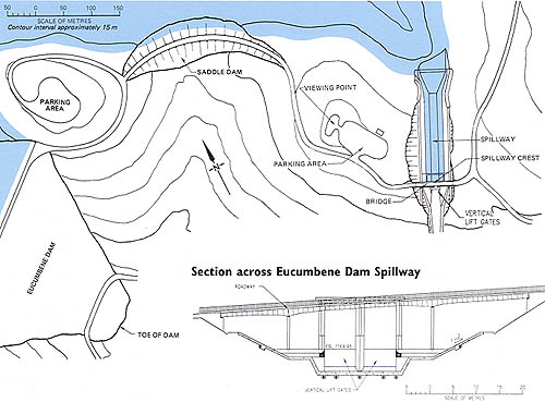
Diversion Works
Before construction activities for the dam commenced, Eucumbene River course was diverted to drain water from the site (Commonwealth of Australia, 1950). As such, it was necessary to build the diversion tunnel for foundation works to begin. As shown in figure 13, the river flows through the end of the diversion tunnel.
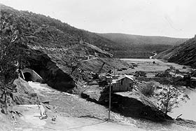
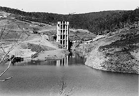
Surrounding trees were cleared to create room for the reservoir while construction of the wall and intake tower proceeded (Snowy Hydro Limited, 2011). The intake tower was constructed at the beginning of the diversion tunnel as shown in figure 14.
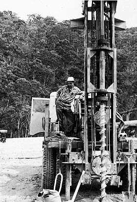
In the grouting process, rock drilling vehicles (figure 15) were used to make holes that were later filled with concrete. This technique helped to reduce leakage, as well as, increase the strength and stability of the dam.
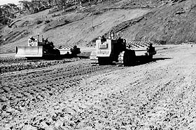
Heavy compaction machines referred to as sheep’s foot rollers (figure 16) were used to stabilize the clay (Snowy Hydro Limited, 2011). The compaction process was conducted in an extremely slow process to maximize the overall outcome.
Tunnels and Tunneling
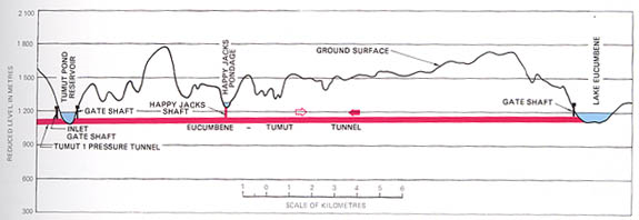
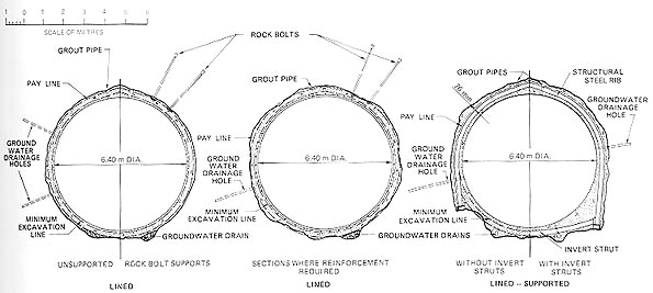
The dam’s construction features are mostly below ground and account for 98 percent of the structural features (Snowy Hydro Limited, 2011). The profile and cross-sections of the Eucumbene-Tumut tunnels are as shown in figure 17 and 18 respectively.
In the scheme, the Eucumbene-Snowy is the longest tunnel spanning 23.5 kilometers in length. Its purpose is to divert Snowy waters from Bend Island for storage in Lake Eucumbene. The tunnel was constructed within four years and has a maximum diameter of 6.3 meters.
Technologies such as rockbolting and the sliding tunnel floor enabled quick and effective tunneling to be realized (Snowy Hydro Limited, 2011). As shown in figure 19, the sliding tunnel floor was a large steel structure used as a task surface, as well as, an equipment carrier.
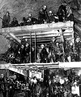
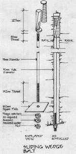
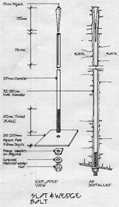
On the other hand, rock bolts were used to reinforce the tops and sides of principal structures like power stations and tunnels (Snowy Hydro Limited, 2011). As shown in figure 20, steel bolts were used to induce an excellent anchor to the parent rock (Mills, 2009). This technique provided a cheaper and safer alternative to concrete lining in tunnel walls. In addition, it reduced the thickness of concrete lining that would be required for pure concrete lining; hence, reducing the overall cost of concrete. In the whole process, the design team discovered that a structural arch was created by placing rock-bolts in a pattern across the tunnel’s roof (Mills, 2009).
Furthermore, special digging tools referred to as pelicans (figure 21) were used to dig the loose material within tunnel walls and roofs.

The “Snowcom” computer (1960) was designed by the University of Sydney and was used for engineering design and calculations for the project. By the application of advanced computer-based techniques, the Snowy Mountains Scheme was completed on time and within budget.
During the entire construction period, industrial safety was a vital concern by the Building Authority. In terms of safety practices, the Scheme was doing better than all existing projects at the time. In 1960, for instance, William Hudson introduced and made compulsory the wearing of safety belts in all Snowy Mountains vehicles. All members in the workforce were required to sign an agreement for the acceptance of wearing a safety belt before engaging in site works.
Hydropower Station
Location
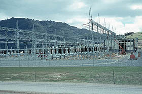
Two of the seven power stations that make up the Snowy Hydropower station are located underground (Snowy Hydro Limited, 2011). These power stations house large generators and turbines which produce the electricity that serves the cities. The water used in hydropower generation is stored in ponds and reservoirs within the scheme (Snowy Mountains Hydro-Electric Authority, n.d.). Figure 22 shows the final stages of construction of Lower Tumut Switching Station that is located at Talbingo.
Problems Encountered
Housing and Amenities
During the initial stages, gathering of technical data was challenging considering that the investigation started after the world war. Besides that, the construction of protected working zones and other important facilities for the workforce proved to be challenging (Gale, 1999). In addition, communication network, road systems, camps, and townships needed to be developed to allow easier flow of construction materials to the site. As a result, several camps, roads and other communication facilities were developed within the region. Furthermore, community services and amenities were a necessity for the construction workforce at the site. Living in camps was extremely difficult, as several people spent the harsh winters in canvas tents with the provision of only basic amenities (Gale, 1999).
Deaths and Safety
During the construction of Snowy Mountains Dam, 121 reported deaths occurred as a result of industrial accidents (Dixon, 1999). Out of these, 26 workers died in accidents involving plant operations such as bulldozers, haul trucks, cranes and tournapulls (Dixon, 1999). Deaths resulting from rockfall averaged 14 workers and occurred were caused by falling objects, explosives, machine accidents and several other cases.
Discussions
As described in the previous section, Hoover Dam, Snowy Dam and Three Gorges Dam employed various techniques during the construction process. Some of the techniques used present some commonality while others are different. In this section, these differences and similarities in the construction techniques and practices are discussed.
Ground Stabilization, Compaction and Grouting Techniques
In all the projects mentioned above, ground stabilization, compaction and grouting techniques were used to ensure the Dams are built on sound foundations. For example, rollers were used to stabilize the clay ground to receive the foundation of the Eucumbent dam. This was done by compacting layers of clay using earthmovers and rollers, as mentioned earlier. Grouting the bases and walls of the river canyon helped to minimize seepage under the dams, as well as, improve their stability. The technique was achieved by drilling several holes into the parent rock and filling them with grout. As such, the desired stability was realized in all the dams and seepage was significantly reduced. Therefore, grouting technique was successfully implemented in all the three dams.
River Diversion techniques
In both the Snowy and Hoover Dam project, main river diversion works were done by the construction of diversion tunnels. As described above, tunnels were driven through the river banks to divert the river from the construction area (Duchemin, 2009). On the other hand, the TGP used highly advanced river diversion technique referred to as river closure method. As such, the associated company successfully conducted three river closures on river Yangtze so that excavation and construction works could begin. Such technological advantages allowed the TGP to be completed successfully within time and budget.
Tunneling Methods
In all the three dams, different tunneling techniques were used to cut through hard rock and other materials. For instance, in the construction of diversion tunnels in Hoover Dam, Six Companies implemented the use of drilling tools and dynamite to drive through the canyon walls. By the aid of gantry cranes, concreting was then done for the tunnel floor areas. Gantry cranes increased productivity and effectiveness of the workforce as materials could be easily moved along the tunnels. To reinforce the walls and roofs of the Hoover Tunnels, 1 meter thick concrete lining was applied to the surfaces. The application was done using movable sections of steel forms and pneumatic guns for the sidewalls and roofs respectively. As such, the tunnels were constructed to allow the diversion of river water from the site without causing damage to the walls.
On the other hand, the tunneling techniques used in the construction of Snowy Tunnels were slightly different as compared to the technique used in Hoover tunnels. For instance, more advanced techniques such as rockbolting and sliding tunnel floor allowed for a faster and effective construction process (Mills, 2009). In rockbolting, steel bolts of different lengths and spacing were helped to create a structural arch; hence, it provided a cheaper and safer alternative than the use of thick concrete lining (Mills, 2009). The sliding tunnel floor was used to carry rail tracks, drilling gantry and other tunneling equipment; thus, making work easier. Combined with the use of the advanced computer based systems, the Snowy Scheme was completed successfully within time and budget.
The more modern Three Gorges Project employed the use of complex techniques in the construction (Veeck et. al., 2007). For instance, tunneling was done using sophisticated Tunnel Boring Machines (TBM) that provides faster, effective and more economical alternatives. Furthermore, modern blasting techniques such as the smooth blasting technique were used. Unlike the Snowy and Hoover blasting techniques, smooth blasting allowed accurate cutting of a reserved layer from the existing rock mass. Smooth blasting reduced excessive shaking that could lead to weakening of the parent rock material.
Concrete Cooling Techniques
As a result of the projects intensity, the quantity of concrete required was enormous and required efficient technologies for successful setting. At Hoover Dam, engineers decided to use interlocking concrete blocks to allow for faster cooling and effective control of heat generated during setting of concrete. As a result, cooling water from a refrigeration plant was forced through a series of pipes running through the interlocking blocks. This helped to dissipate heat from the blocks; thus, effectively preventing crumbling of the structure.
On the contrary, massive concreting was easily done at the TGP due to the availability of intensive temperature control techniques. Several temperature control techniques such as triple pre-alarming systems enabled effective control of temperature in the TGP project. These techniques allowed concrete temperature to be monitored in various ways such as during placement, setting and at different working temperatures. Through this method, the concrete successfully cooled without developing cracks and other flaws.
Conclusions
More than a century ago, various construction techniques had already been developed and were already being put to practice. Dam construction happened to be among the most fascinating constructions that were created in those early times. Dams were constructed for key purposes such as floods control, power generation, and irrigation purposes. These were massive projects considered as state projects. In the modern world, however, more extensive projects such as the Itaipu Dam Project (Brazil) and the 600 kilometers Three Gorges Dam (China) are being constructed. These projects utilize the waters for hydropower generation, irrigation and control of river flooding (Veeck et. al., 2007).
The construction of dams consumes a lot of resources like concrete, steel, rocks, earth, labor and time. An excellent example is the Snowy Mountains Scheme that used more than 100,000 people to construct and complete the dam in 25 years. During the construction, various developments came up such as creation of townships, communication lines, and a network of roads. However, early dam construction engineers faced several difficulties such as technological limitations, accessibility problems and other associated problems.
The modernization of construction management equipment has provided a better, faster, and cheaper way of addressing construction difficulties. For instance, technological advancement has enabled the development of advanced computer based programs that assist in making complex calculations for strength tests, costing, and scheduling purposes. In comparison to the “Snowy Computer” that contained 2048 bytes of memory, modern computers possess an immeasurable capacity to solve complex problems in short durations. In the TGP project, computers were used for several functions such as in the river closure technology, alarm systems for concrete cooling, and in Tunnel Boring Machines. These technologies enable easier management of construction problems and keeping of construction activities within the scope of operation. In the long run, successful results are realized by the team.
Other technological advances have also initiated the possibility of safely undertaking rather dangerous activities. For instance, in the earlier construction of the Snowy Mountains Dam and Hoover Dam, several lives were lost due to falling objects, explosives and extreme temperatures. In modern times, more safety precautions and activities are used to ensure that fatalities are minimized if not exist at all. During the construction of the Bullocks-Ski Tube Tunnel, for example, Kumangai Transfield used a tunnel boring machine to construct a 6.3 kilometers tunnel (1984-1988) and no single death occurred (Dixon, 1999). Furthermore, techniques such as smooth blasting prevented excessive vibrations; thereby, enabling precision blasting.
Despite the numerous benefits linked to the construction of Dams, there are still several issues to be addressed. Examples of such problems include; relocation of people, ecological insignificance, and health hazard among others (Steil & Duan, 2010). As a result of the massive nature of the projects, people living in the identified areas are relocated to allow commencement of construction activities. In the TGP project, for example, more than 1.3 million people had to be relocated to allow construction activities to commence (Steil & Duan, 2010). Furthermore, the enormous structure of the dam posed as an ecological threat and caused the loss of historical sites in China (McGill University, 2001). However, the overall benefits of the scheme should be put to picture for people to realize the attached value. In conclusion, it is inevitable to mention that continuous advancement in technology will allow most of the construction related challenges and associated problems to be fully addressed.
References
Allen, M. (1983) Hoover Dam & Boulder City. CP Printing & Publishing. Redding: CA.
Barber, P. (2010) Hoover Dam Construction. Web.
Bureau of Reclamation. (2006) Reclamation: Managing Water in the West: Hoover Dam. US Department of the Interior.
Commonwealth of Australia. (1950) Diversion and Utilization of the Waters of the Snowy River: A final Report of Commonwealth and States Snowy River Committee. Commonwealth of Australia.
Deyong, X. (2006) Construction Technology and Management Experiences on Yangtze River Three Gorges Project. Assistant of General Manager: China Gezhouba (Group) Corporation.
Dixon, E. (1999) Death in the Snowy. Web.
Duchemin, M. (2009) “Water, Power, and Tourism: Hoover Dam and the Making of the New West”. California History 86 (4): 62–74.
Dunar, J., & McBride, D. (2001) Building Hoover Dam: An Oral History of the Great Depression. Reno, Nev.: University of Nevada Press.
Gale, S. (1999) The Snowy Water Inquiry: Food, Power, Politics and the Environment. Australian Geographical Studies, 37(3), 300-304.
Hiltzik, A. (2010) Colossus: Hoover Dam and the Making of the American Century. New York: Free Press.
McGill University. (2001) Three Gorges Case Study. McGill University. Web.
Mills, W. (2009) The Snowy men Behind Tunnel Rock Bolting. Cooma, N.S.W. Australia.
Power Technology. (2011) Three Gorges Dam Hydroelectric Power Plant. Web.
Snowy Hydro Limited. (2011) Snowy Mountains Scheme. Web.
Snowy Mountains Hydro-Electric Authority. (n.d.) Engineering Features of the Snowy Mountains Scheme. Granville, N.S.W. Australia: Ambassador Press Pty. Ltd.
Steil, S., & Duan, Y. (2010) Policies and Practice in Three Gorges Resettlement. Web.
Stevens, E. (1988) Hoover Dam: An American Adventure. Norman, OK: University of Oklahoma Press.
True, J., & Kirby, T. (2009) Allen Tupper True: An American Artist. San Francisco: Canyon Leap.
Veeck, G., Ponnell, C., Smith, C., & Huang, Y. (2007) China’s Geography Globalization and the Dynamics of Political, Economic, and Social Change. New York: Rowan and Littlefield Publishers Inc.
Williams, P. (2009) Damming the Three Gorges: Dam Safety Analysis. Web.