- The Key Components of an Image-Intensified Fluoroscopic System
- Flat-Panel Detector (FPD) Types
- Digital Fluoroscopy Using Flat-Panel Detector
- Components of the Cesium Iodide Amorphous Silicon Indirect-Capture Detector
- The Scintillator Layer
- Photodetectors and TFT Arrays
- Direct Conversion Flat-Panel Detectors
- Image Display
- References
The Key Components of an Image-Intensified Fluoroscopic System
- X-ray tube.
- Spectral shaping filters.
- Collimator.
- Anti-scatter grid.
- Image receptor.
- Image processing computer.
- Monitor.
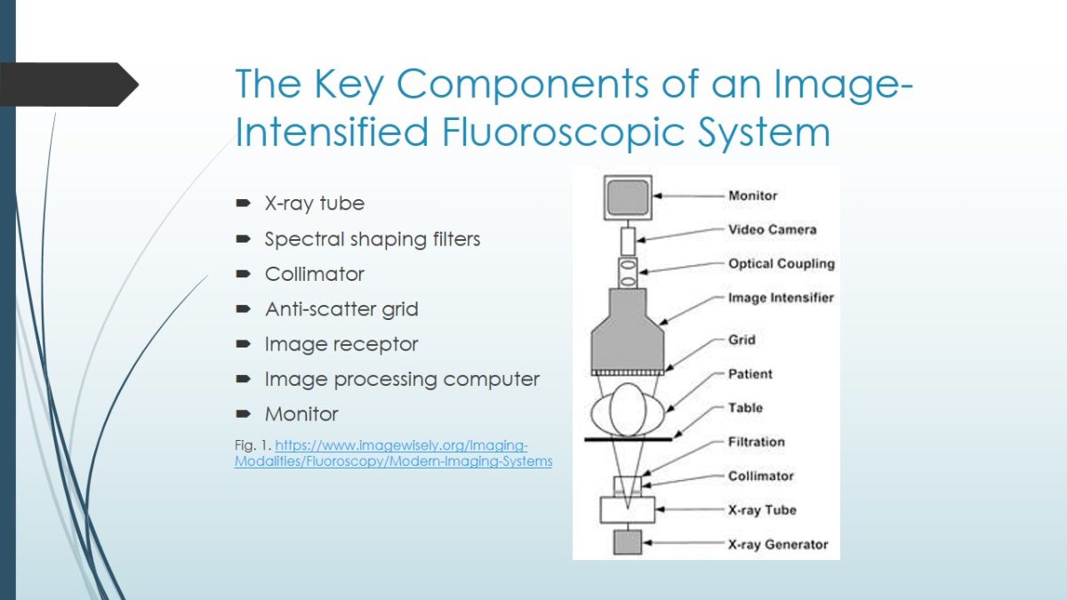
An image-intensified fluoroscopic system consists of the following components: an X-ray generator, x-ray tube, collimator, filtration, grid, image receptor, image processing system, and a display (Gingold, n.d.). X-ray tubes expose radiation either in a continuous or pulsed manner. A collimator limits the extent of the X-ray field. The filtration elements allow choosing between low and high dose modes during the procedure. Anti-scatter grids are used when the procedure is performed in high-scattered areas, such as the abdominal ones. The image receptor can be either an x-ray image intensifier or a flat panel detector. This presentation will focus on the flat panel detector.
Flat-Panel Detector (FPD) Types
- Indirect conversion:
- outermost layer: phosphor screen;
- detector: based on amorphous silicone photodiode;
- convert X-rays to light and then to charge.
- Direct conversion:
- outermost layer: high voltage bias electrode;
- detector: based on amorphous selenium;
- convert X-rays to charge directly.
Flat-panel detectors (FPD) are used in digital fluoroscopy and radiography to convert X-rays to charge or light. There are two types of FPDs: direct and indirect. Direct conversion FPDs convert X-rays directly to charge while indirect conversion FPDs convert X-rays to light first and then to charge. The detectors of the direct conversion FPDs are based on amorphous selenium while the detectors of the indirect conversion FPDs are based on amorphous silicon photodiode. Their outermost layers differ as well. Direct conversion FPDs have high voltage bias electrodes while indirect ones use phosphor screen.
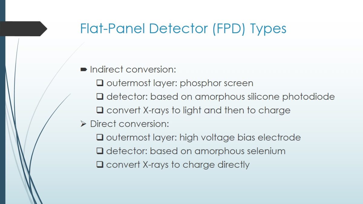
One can see the differences between the two types of FPDs. Direct conversion FPDs convert X-rays into a charge. After that, the charge is processed by a TFT (Thin Film Transistor) or CMOS (Complementary Metal Oxide Semiconductor) array. The processed electric charge is sent off to the computer, where it is processed and converted. Indirect conversion FPDs involve some additional processes in the conversion. The first layer converts X-rays to light. The next thin layer (Amorphous silicon) converts light to an electrical charge. After that, photodiodes are doped and sent off to a computer too.
Digital Fluoroscopy Using Flat-Panel Detector
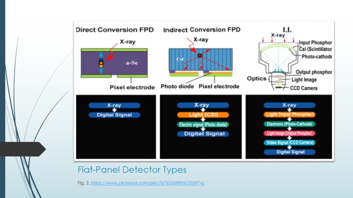
An advance in digital fluoroscopy is a flat panel detector used instead of an image intensifier. In this image, you can see an example of a digital X-Ray system that uses a flat panel detector. This fluoroscopy system minimizes scatter radiation and is safe for both patients and staff. It also helps to reduce panning time because it does not require a barium swallow. Moreover, image quality is higher, which leads to better diagnosis and health outcomes.
Components of the Cesium Iodide Amorphous Silicon Indirect-Capture Detector
- The scintillator;
- The photodetector;
- A TFT array:
- Readout;
- Charge collector;
- Light-sensitive elements.
The main components of the cesium iodide amorphous silicon indirect-capture detector are the scintillator, the photodetector, and a TFT array, which consists of a readout, charge collector, and light-sensitive elements. The panel is arranged into detector elements and is covered by the scintillator plate. Each detector element, or pixel, contains a photodetector and a TFT. A TFT is an electronic component layered onto a glass substrate that includes a readout, charge collector, and light-sensitive elements. Each part of the indirect-capture detector has a particular function, needed for image production.
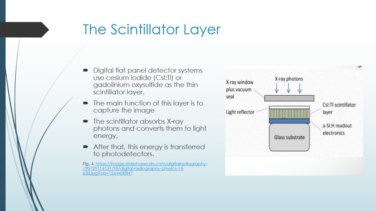
The Scintillator Layer
- Digital flat panel detector systems use cesium iodide (CsI:Tl) or gadolinium oxysulfide as the thin scintillator layer.
- The main function of this layer is to capture the image.
- The scintillator absorbs X-ray photons and converts them to light energy.
- After that, this energy is transferred to photodetectors.
Most modern digital flat panel detector systems use a thin layer of cesium iodide or gadolinium oxysulfide as the scintillator (Bushong, 2013). The role of this component is to capture the image. The visible light is coated onto the photodiodes’ active matrix array. The scintillator absorbs X-ray energy and converts it to light energy.
Photodetectors and TFT Arrays
- Amorphous silicon photodiode arrays.
- Charge-coupled devices, or CCDs.
- Photodetectors gather this light energy and convert it into electrical charges.
- TFT arrays capture and isolate each pixel element, received from photodetectors.
- TFT transmits these electric charges to the monitor for display.
There are two types of photodetectors used in indirect conversion systems: amorphous silicon photodiode arrays and charge-coupled devices, or CDCs. The role of photodetectors is to convert light energy into electrical charges. After that, these electric charges are transmitted to the TFT arrays, which, in turn, capture and isolate these pixels, convert them and transmit them to the image processor for display. The charge can be released and read if a high potential is applied at this stage. In such a way, an image appears on the screen.
Direct Conversion Flat-Panel Detectors
- Consists of high-voltage bias electrode, or a layer of x-ray photoconductor.
- X-ray photoconductor is used instead of scintillator.
- X-ray photoconductor directly converts x-ray energy into free electrical charge carriers.
- Amorphous selenium photoconductors are the most popular among other photoconductors.
Direct conversion flat panel detectors (FPDs) differ from the indirect conversion FPDs since they convert X-rays directly to charge, omitting the light-conversion stage. One of the most popular direct conversion FPDs is amorphous selenium. It consists of a high-voltage bias electrode, which is called an X-ray photoconductor. This photoconductor is used instead of a scintillator. The principle of image processing will be shown on the next slide.
On this image, one can see the processes of image capture, conversion, and readout in the direct conversion. Thus, X-rays are attracted to the surface electrode, which is charged positively. Then, these X-rays cause the creation of positive and negative charges. The selenium layer electrode draws positive charges to the storage capacitator, where a latent image is produced. Finally, this latent image is read with the help of an electronic array, typically by the TFT array. Direct conversion eliminates the optical conversion step, thus providing high spatial resolution.
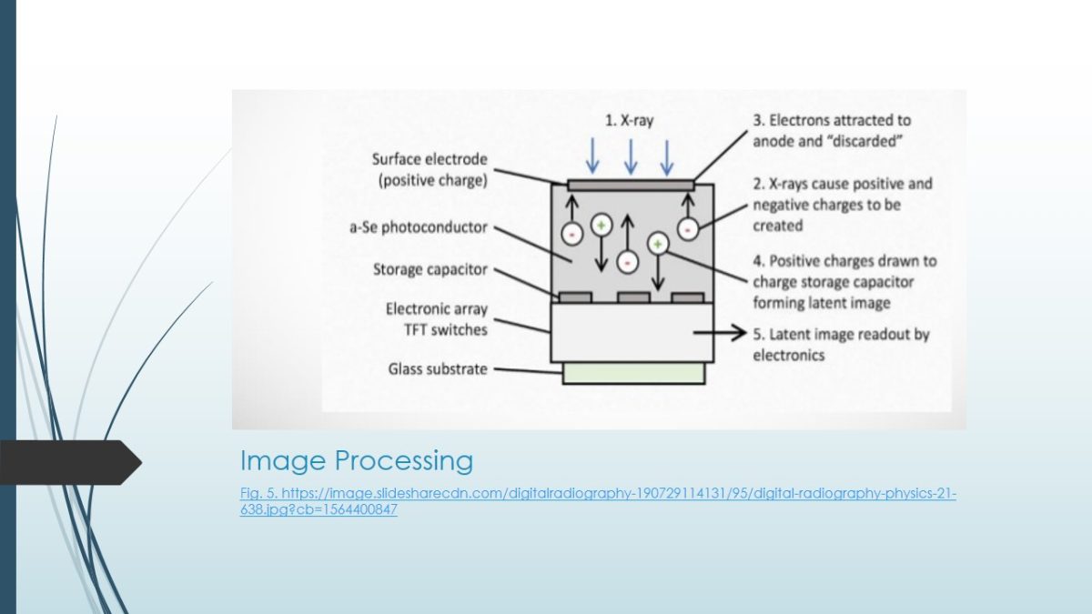
Image Display
- Television monitors are the oldest displays.
- They consist of an electron gun that scans the phosphor layer on the inside of the monitor’s glass.
- Modern image display systems feature liquid crystal display (LCD) monitors.
- These displays consist of several layers, with the liquid crystal layer sandwiched between polarizing films.
- Plasma monitors differ from LCD monitors, having a thin layer of pixels instead of the liquid crystal layer.
- Recording systems.
The final step of the fluoroscopy process is an image display. There are several types of monitors. The oldest one is a television monitor. However, since modern fluoroscopy requires high-quality image and video displays, LCD and plasma monitors are widely used nowadays. After the image is projected to the monitor, a recording system may be used to record the video.
References
Bushong, S. C. (2013). Radiologic science for technologists: Physics, biology, and protection (10th ed.). Elsevier.
Gingold, E. (n.d.). Modern fluoroscopy imaging systems. Image Wisely. Web.