Introduction
This paper responds to the requirement for a 37,000 DWT product tanker vessel, with a draft of 11.5 meters, an overall length (LOA) of 180 meters, a beam of 26 meters, 12 main tank compartments plus two for the oil-water slops, 20,300 Gross Register Tonnage (GRT) for the total internal volume, 10,150 Net Register Tonnage (NRT) for cargo volume and double hull construction.
Seagoing transport came into use starting in 1863, soon after the first commercial crude oil wells began production in Philadelphia. As long as demand was limited to replacing fish, vegetable or whale oil for lighting, breakbulk shipping was the norm. That is, even the first exports overseas to the UK were shipped much the same way navies and the merchant marine had always done with rum, drinking water, molasses and other liquids: in oaken casks or steel drums. By 1871, domestic demand in the U.S. had developed to the point where local deliveries required bulk shipping, via oil tank barges and the type of cylindrical railroad tank-cars one still sees today. This period also saw the development of, first, sail-powered tankers in 1863 and, as technology developed, steam-driven tanker vessels a decade later.
Many of the most basic structural and safety issues were addressed from the earliest days of the tanker-fabrication industry. Within the same decade as Belgium’s Vaderland (see section V. “Safety Matters” below), Ludwig Nobel of the Azerbaijan-based Branobel oil company had commissioned a self-propelled tanker ship design that addressed structural and safety issues. The design had to permit petroleum products to contract or expand as ambient temperatures varied, the tank compartments had to have a way to vent fumes rather than be hermetically sealed, and both the liquid and cargo had to be prevented from leaking into the engine room or the high heat from boilers would ignite the former. The result was the Zoroaster (1878), followed by two more of the same design commissioned in the same year.
The Vessel Classes
The tanker designated for this analysis is among the smaller modern classes, in the middle of the “Medium Range tanker” class (see below). Nonetheless, the tasked vessel is a far cry from the first successful prototype, the aforementioned Zoroaster. At 10,150 NRT, the assigned vessel is nearly 42 times more capacious than the Zoroaster. The latter had a LOA of 56 meters (less than one-third as long), a beam of 8.2 meters (versus 26) and a draft of just 2.7 meters. Such comparatively modest dimensions stemmed from the fact that the Zoroaster had to transit inland waterways between the producing fields at Riga and St. Petersburg, thence emerging at the Baltic for the final run to Sweden. The inland transit consisted of the Volga River, the Rybinsk and Marinsk Canals, Lakes Ladoga and Onega.
The Second World War was a watershed for tanker capacity, owing to the need to move troops and supplies across the two oceans. As well, replacements were needed for operational losses, chiefly due to German submarine ‘wolf pack’ tactics in the North Atlantic. The most widely-built class at this time was the T2, 162 meters LOA (only slightly shorter than the vehicle under consideration) but at a capacity of 16,500 DWT, just half what the tanker under consideration is to be. When the conflict ended, most T2s were sold off and saw civilian use until the 1970s.
A significant reason for the development of the ULCC class – up to 400 meters LOA and 500,000 DWT in rated capacity – was the closing of the Suez Canal in 1956, a consequence of the war fought between Egypt on one hand and France, Israel and Great Britain on the other. It became necessary for tankers to once again sail around the Cape of Good Hope to transport Persian Gulf and refinery products to the principal refinery complexes in Europe, such as Rotterdam. With larger size came economies of scale.
Two years after the Suez Canal blockade, American shipowner Daniel K. Ludwig became the first to float a tanker of 104,500 long tons displacement. By 1979, technological advances permitted Japan’s Sumitomo to construct the largest ULCC ever. Built for the Persian Gulf-Japan route, the Seawise Giant boasted a LOA of 458.45 meters, displaced 564,763 DWT, had 46 tank-compartments, and a draft of 24.6 meters (Singh 23).
As a product tanker, this assigned vessel tasking will primarily load refined petroleum products (e.g. gasoline, diesel, avgas/kerosene) or other processed industrial chemicals. By capacity, the planned vessel is a medium-range tanker as shown by the class categories below (Evangelista 7).
- 10,000–24,999 DWT: General Purpose tanker
- 25,000–44,999 DWT: Medium Range tanker
- 45,000–79,999 DWT: Large Range 1 (LR1)
- 80,000–159,999 DWT: Large Range 2 (LR2)
- 160,000–319,999 DWT: Very Large Crude Carrier (VLCC)
- 320,000–549,999 DWT: Ultra Large Crude Carrier (ULCC)
Under the International Association of Classification Societies (IACS) general categories, a petroleum products tanker of the assigned capacity and dimensions would fall midway between the two smallest classes, the “Seawaymax” and “Panamax”, in capacity and beam but require nearly as much berthing depth as the latter class. The planned vessel is shorter in length than either class.
Table 1: General Tanker Classifications and Dimensions (Source: IACS)
Size is important because the very largest tanker classes are highly cost-efficient. A ULCC, for instance, spreads loading, shipping and offloading overhead through such large product volumes that contribution to retail cost at U.S. service stations is as little as two cents per gallon despite the great transit distances and insurance rates involved.
The trade-off is that “supertanker” VLCC’s and ULCC’s have such deep drafts at full load that they cannot dock at most ports. Even emptied of ballast, supertankers must load at off-shore platforms and single-point moorings, essentially small floating pumping stations connected by underwater pipelines to the main depots onshore. At their destinations, such facilities are not always available. Hence, supertankers offload at lightering stations to barges and tankers of the Seawaymax and Panamax class (from 10,000 to 80,000 DWTs). This way, the crude or refined product can still reach depots far inland over available waterways.
Table 2 below suggests that the vessel subject of this paper does not normally work the long-range routes handled by VLCC’s, ULCC’s, and the Suezmax classes. Even the comparatively moderate distances involved in cross-Mediterranean trade is handled by tankers of at least the Aframax class.
Table 2
Nonetheless, the tanker to be constructed can do quite a brisk trade plying the Caribbean routes, from petroleum surplus nations and regions such as the U.S. Gulf Coast, Mexico, Venezuela and Trinidad-Tobago to the refinery complexes in Texas and the U.S. East Coast.
On a final note about operational life, at last count (2005), the average age of operational tankers globally was 10 years; one-third were fairly new, being less than four years old, while just half as many were more than 20 years old at the time. That same year, 475 tankers were completed, for a worldwide new capacity of 30.7 million DWT. This new capacity was 50% better than the 20.8 million DWT attained as recently as 2000. More importantly, 81% of the new tonnage in 2005 comprised tankers smaller than the Aframax class, suggesting that the vessel subject of this paper is in the most widely-utilized tanker class.
Structural Elements
Architectural Solutions
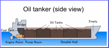
The basic tanker design of contemporary times (see Figure 1 below) has evolved since the earliest self-propelled tankers were designed by Ludwig Nobel and Sven Almqvist in the late 1870s, nearly a century and a half previously. The Zoroaster had the engine room amidships with a tank for the original cargoes of kerosene forward and aft. In addition, Nobel innovated with an integral pipe connecting the tanks, which at least avoided the extra weight of metal pipes leading to exterior access points.
That first design already featured watertight compartments, twenty-one in all, for buoyancy more than safety. After all, a great part of the Zoroaster’s voyages were on the inland waterways that ran from Riga to the Baltic, thence to its homeport in Sweden. Not being of a mind to patent this first seagoing, self-propelled tanker, Nobel basically tolerated copying by an entire generation of shipwrights and oilmen of the time.
Hull Designs
It is fully intended that the vessel subject of this paper should be double-hulled. This is a major consideration in tanker architecture, the main reason being the risk of a collision or other accident spilling the contents of the vessel to the surrounding waters.
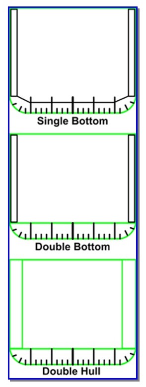
Tanker design pioneer Ludwig Nobel thought nothing of employing the intuitively logical single-hull design for the 11 vessels he commissioned between 1878 and 1880. Having just a single layer of metal plate between the flammable cargo and the sea may not have seemed very perilous at the time since the Branobel fleet traversed well-traveled lakes, canals, and the Baltic. This is also a logical thing to do for the test tanker if it were to be chartered solely on that route, where storms are rare except in winter and there are ample non-rocky anchorages. There are practical reasons, however, for designing the test tanker as a double-hulled vessel if, like many in its size class, it is chartered for cargoes in the busy sea lanes of the Caribbean.
As Figure 2 (above) shows, the distinguishing feature of the double-hull design is the empty space separating the two layers of steel plate that makeup both the tanker bottom and sides. The reinforcing steel beams subdivide that intermediate space but are not necessarily watertight. In contrast, both plate layers must be watertight or they do not serve the purpose at all. Hence, it is also false economy to adopt only the hybrid design of designing in just a double-bottom hull (the middle schematic in Figure 2) because this offers some protection solely from running aground on a reef or rocky shore and then only when the force of impact is not enough to penetrate the inner bottom. The single-side hybrid design offers minimal protection in a perpendicular or bow-on collision.
In any case, regulatory pressures have increased owing to the Exxon Valdez (1989, spilling nearly one-fifth of its cargo of 54.1 million gallons of crude on running into Bligh Reef in Alaska, blamed largely on crew errors and mechanical failures), Prestige (2002, broke up off Galicia in northwest Spain after being turned away by three governments), and the Erika (1999, broke up off Brittany in stormy seas when refused refuge) disasters. As a consequence, the European Union will bar entry to single-hulled tankers commencing 2010. No less than the United Nations has called for a global phase-out of mono-hull tankers, also by the end of this year, while the International Convention for the Prevention of Pollution from Ships, approved as far back as 1973, has set the deadline at 2026. In response to the Exxon Valdez spill, the United States Congress passed the Oil Pollution Act of 1990 (OPA-90), which barred single-hulled tankers from entering its waters starting 2015. Naturally, this last directly affects the vessel subject of this paper since it is in a class popular for Caribbean-to-USA-East-Coast charters.
After consulting with industry experts, the U.S. National Academy of Science Marine Board released a report nine years after Exxon Valdez pointing out that double-hull tankers offered the advantages of:
- reducing the need for saltwater ballasting of the tanks themselves and therefore minimizing corrosion;
- speedier ballasting of the space between the two hulls in an emergency;
- more rapid cargo offloading;
- ease of tank cleaning when the nature of the cargo changes; and,
- the primary benefit (mentioned above) of tank integrity being breached during grounding or in the course of a “low casualty” collision.
The same report acknowledges that constructing a double-hull design is not only inherently more costly (two plates of metal versus one for the single-hull) but also requires special outfitting. For one, protecting the integrity of the space between the two hull layers means access for cleaning, inspection, venting fumes, and integrity inspection take more effort. More vapor detectors are needed for the otherwise empty space between outer hulls and tanks.
Afloat, double hulls cannot fully protect from spillage in a high-speed collision, grounding on a rocky shoreline or reef, crew errors, and sloppy inspection for corrosion. These are not, of course, concerns that can be addressed in tanker architecture and construction.
Design Alternative: The Coulombi Egg Tanker
In a high-energy casualty, both of the double hulls can still be breached and thus cause oil to spill to the surrounding waters. One way to minimize the amount spilled is to use smaller compartments for tanks (see the following section) or to have the more honeycombed cross-section known as the Coulombi Egg.
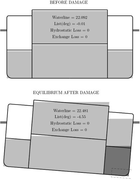
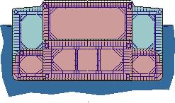
Distinctive to this design is the stepped deck and the larger space between inner and outer hull. The white segments in Figure 3 (aqua in Figure 4) are empty in a normal state. Any low- to medium-casualty collision above the waterline should therefore simply buckle in the outer hull, notably because one can see from Figure 4 that there are plenty of cross-braces on all sides. Even a high-impact collision should result in some of the oil merely spilling over into the empty bulkhead. In short, spills to the surrounding ocean are lower than in a traditional double-hull design with a narrower gap between the inner and outer hull. Such a larger empty area is also easier to monitor for corrosion, clean and monitor for flammable vapor build-up.
A below-waterline breach such as might happen on hitting the ice or an unknown shoal (see dotted rectangle in Figure 3) lets seawater in but because the crude or other refinery product is lighter, the latter vents to the empty “tank above it. Being now heavier on the side where the breach occurred, the tanker lists by between four to five degrees. And yet, the larger upper ‘vent’ tank does not spill oil to the sea.
While such architecture is theoretically sound, the fact is no ship has yet been built using this design. Moreover, the U.S. Coast Guard considers the Coulombi Egg a single-hull design and this severely limits the charters such a tanker might service.
Multiple Tank-Compartments
The schematic in Figure 1 (page 7) shows a total of five compartments. A multi-compartment design has been part of tanker architecture beginning about five years after Branobel began designing tankers for its own use. The main reason for creating multiple compartments was to neutralize free surface effect, the tendency of the transported liquid to slosh opposite the direction of travel or, in storms, from side to side. Unless limited to a minimum, free surface effect in a single hold could so shift the center of gravity that the tanker might easily capsize.
The solution was to divide the hold into several which run across the beam of the ship. In addition, a longitudinal bulkhead ran fore and aft to bisect the holds and thus forestall full side-to-side movement of the cargo.
Structure and Ship Strength
Strength is the most fundamental criterion when evaluating tanker structural design owing to the loads the vessel must withstand over its expected service life. Hence, the shipyard architect must design for structural strength while taking into account load type, charter requirements, contemplated life cycle and service conditions when designing vessel structure. And yet, a tanker that is over-engineered is uneconomic for being too heavy, adding unnecessary loads on the propulsion system and reducing freeboard.
Major Factors Impinging on Structural Strength of Tanker
The total load on any singular section of the tanker is the combination of primary, secondary and tertiary hull loads, strength and bending, typically calculated in quick fashion by testing a plate of the bottom hull, midway between braces/beams, halfway between bow and stern, and midway across the beam.
By definition, primary strength and bending pressures are principally the longitudinal loads that affect the entire hull from bow to stern. Other than structural and oil cargo load factors, primary wave loads are the primary reason tankers sag (lower in the center from true horizontal) or hog (bend upward in the center). A wave with a length equal to the tanker hull can cause both as the peak reaches bow and stern simultaneously and then moves toward the middle of the vessel.
The basic strength calculation considers the entire structure of the tanker as a unitary beam, the longitudinal bending strength of which is estimated from the simplified Euler-Bernoulli beam equation applied to the neutral point or central axis of the beam thus:
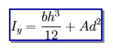
where Iy is the moment of inertia across the length of one tank compartment, b is the width (also the beam) of that hull section, h is the height of the main hull structure (excluding the superstructure), A the surface area of the section, and d the vertical distance from the neutral axis to the notional center of the tank compartment.
This assessment of longitudinal bending strength is augmented with:
- vessel weight and buoyancy pressure for the empty index compartment,
- the weight of the petroleum in that compartment (NRT-10, 150 / 12 compartments = 845.8 tonnes),
- corresponding buoyancy for the load tonnage in that compartment,
- assumptions made about still more bending due to wavelength and height encountered when the tanker vessel is in transit between ports.
Being calculated by tank or bulkhead section, the secondarily loads on a tanker is primarily compressive as a function of outside water pressure and the combined weight of the hull itself, the cargo, superstructure and engine. Finally, tertiary loads are calculated on the smallest area of all, hull plate sections bounded by stiffeners and beams.
The fourth load and strength consideration, finally, comprises the way the 12 contemplated compartments are sized and distributed throughout the hold, and therefore contribute to structural strength and stability, as well as facilitate pumping the crude in/out. This means arranging the main storage tanks, pipes, pumps and ballast tanks to contribute to all the above criteria. At the very least, loading and offloading should be as even as possible from all tanks that hold the same liquid to avoid undue pressures on structural strength such as: transverse shear, bending and torsion. Uneven distribution of the oil tank/cargo holds also causes significant point loads on the structure, which risks bending forces on the hull when different from the distribution of buoyancy from displaced water.
Designing for structural strength also means compensating for localized stress and accounting for the full complement of machinery and other equipment on deck, on higher levels of the superstructure and at least two levels below deck; these include electric motors, the main turbines, pumps, cranes, derricks, and mooring equipment. Thus, it might be that a tanker of the contemplated dimensions may have a surface area of 3,600 to over 4,000 square meters but closer inspection may well reveal that the main crane and pump systems are all grouped within a 10 square meter area of the main deck supports, which therefore need to be strengthened.
These are all the bending loads which the primary hull beam must be strong enough to resist the catastrophic breakup of the ship’s hull.
Load Types Exerted on Marine Structures
Designing for structural strength therefore means taking into account standard and extreme loads on the tanker as system, counting structure, the aforementioned clusters of equipment installed and liquid cargo. The standard loads on all three are operational, comprising hydrostatic forces (still water and wave buoyancy), lift loads, wind pressure notably on the superstructure, support points when in dry dock and the concentrated loads of mooring lines, anchors, and hawsers.
Though rare in occurrence because they are force majeure events, extreme loads owing to collisions with other vessels, grounding, slamming and wave action in adverse weather can be the true test of whether the tanker architect had designed enough strength into the basic structure of the tanker vessel.
Structural Rules
Acknowledging that its ten classification member-societies adhered to outdated and inconsistent structural rules, the International Association of Classification Societies proposed certain harmonization measures at Rio de Janeiro in April 2006. Among the highlights:
- Assumptions for durability/fatigue must use extreme standards such as being able to survive 25 years (at minimum) in the often-harsh and stormy conditions of the North Atlantic.
- Class inspections should rigorously take into account visible corrosion and deduct the corresponding margin from the original strength estimates at design and when launched.
- Inspection for, and insisting on the replacement of, evident weaknesses such as yielding or compressive buckling.
- The new vessel under consideration is covered by common structural rules for double-hull tankers over 150 meters LOA.
- Scantling requirements must match strength checks at vessel launch with periodic in-service review criteria.
In addition to the above, the published Common Structural Rules for Tankers (Bureau Veritas 5-12) and for Bulk Carriers provide the following guidelines for the contemplated vessel:
- Bulkheads – Requiring a minimum of three watertight bulkheads: bow collision bulkhead, an aft peak bulkhead and (if the latter comprises the aft bulkhead for the engine room) one more separating the main cargo holds from the engine space. Further bulkheads that subdivide the cargo holds should be equally spaced (as far as practicable), permit flooding in an emergency, and maximize stability in case of the outer and inner hulls have been penetrated in an accident. It is advised that the collision bulkhead is at 0.05 LL (9 meters for the contemplated LOA of 180 meters) or 10 meters from the forward reference point, whichever of the two values is lower.
- Ballast Tanks – should be of such capacity that the contemplated tanker can voyage safely without recourse to pumping seawater into the main cargo holds. Specifically, the “moulded draught amidships…should not be less than Tmid = 2.0 + 0.02L m where L = rule length.” (Bureau Veritas 7)
- Double Bottom Depth – should be no less than one meter where molded breadth in meters is divided by a factor of 15. The alternative measure is ddb = 2.0, also in meters.
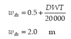
- Double Side Width – should also be no less than one meter or the lower of the two values below. Since the design specification is for 37,000 DWT, the value for the first equation is slightly longer at 2.35m than the second.
- Cofferdam spaces – should be airtight, to prevent vapor build-up from escaping.
- Placement aft of cargo spaces – Aside from the engine room, the cargo pump room, main cargo control stations, control stations, crew bunks and other service spaces must all be aft of the main cargo holds.
Safety Matters
Safety concerns go all the way back to the advent of steam-driven tankers. When an American shipyard finished the first such vessel in 1873 for a Belgian oil importer and distributor, the authorities in both nations were so apprehensive about the proximity of coal-fired burners to tanks of flammable petroleum that they imposed restrictions on the Vaderland.
The first oil tanker disaster struck the Branobel vessel Nordenskjöld, though it involved not structural or design issues but offloading pipes that were disconnected when a gust of wind struck the vessel in port. The kerosene spilled onto the deck and down to the engine room where it ignited and the explosion killed half the crew.
After World War I, a mistaken attempt to convert surplus cargo vessels to petroleum tankers using riveted tanks resulted in another lesson learned. Not being hermetic enough, the riveted tanks on the Phoenix leaked, built up into explosive fumes and caused an explosion. Owner Daniel Ludwig himself narrowly escaped being killed, with the result that he and other owners switched completely to welded tanks.
Regardless of the integrity of modern compartment-tank fabrication methods, petroleum cargoes are inherently volatile and readily build up into flammable vapors. Hence the critical importance of equipping the contemplated tanker not only with proper venting but also an inert gas system that will prevent hydrocarbon vapors from mixing with ambient oxygen. Whatever equipment and inert gas are installed, it should work to simultaneously raise the lower flammable limit (lowest concentration at which the vapors will ignite) and bring down the upper flammable limit. The goal is to reduce oxygen concentration in the holds and tanks to about 10 or 11 percent, at which point the flammable range is virtually zero. There should also be enough inert gas-oxygen mixture (the latter at about 5% of volume) stored onboard to completely displace air in the tanks when emptied at offloading.
Rather than fires and fatal accidents, however, it is public reaction to high-profile oil spills that impels pressure for more stringent design and operating regulations. And it is the volume they carry that makes tankers especially risky. Reviews conducted by both the U.S. Coast Guard and the International Tanker Owners Pollution Federation are basically in agreement: the greater number of spills come from lighters, barges, production facilities, pipelines, and non-tanker ships but the average tanker spill involves about a hundred times more volume.
Other deck features and fixtures considered standard for operating efficiency, safety and stability of the contemplated tanker go back to the first generations of the vessel genre. The Glückauf (completed in 1886) already boasted pipes connecting all tanks, valves operated from deck level, a line to vent hydrocarbon vapors, empty compartments in between the main tanks (also termed ‘cofferdams’), and facilities to load seawater ballast when empty of cargo.
Flags of Convenience
By Central Intelligence Agency count, the global fleet of tankers with at least 1,000 long tons DWT displacement numbered 4,295 oil tankers as of 2007. Only around one percent were registered in either the U.S.A. or the U.K., partly because the beneficial owners were based elsewhere anyway but principally because of the distinct advantages offered by flags of convenience.
Other states that opened shipping registries have more relaxed regulations for vessel and equipment upkeep, as well as for crew and officer credentials. They are also more likely to shift the burden of certification and inspection from maritime or shipping regulators to the classification societies (i.e., the IACS members). Where the owner of the contemplated tanker is inclined to change class for economic advantage in the future, registering and sailing under a flag of convenience makes it easy.
Panama and Liberia were the first to come forward with open registers. Consequently, the two Third World nations currently account for the bigger shares of the worldwide tanker fleet at 12.3 percent for Panama and 10.8 percent for Liberia. Other popular flag states are Singapore, China, Russia, the Marshalls and the Bahamas.
A Panama registration is a two-stage process whereby the shipowner submits the documents for the Provisional Registration valid for from six to nine months and a Permanent Registration, which has a four-year validity. The documents to be submitted to either the General Directorate of the Merchant Marine in Panama or three consulates elsewhere:
- Preliminary Registration Application Form (English version available only from the foreign offices.
- registration of ship title (for owners).
- registration of mortgage (if applicable), and the following supporting documents:
For GRT of 20,300, the applicable fees are: US$3,530 for initial registration fee, $525 for the “Provisional Patente & Radio License”, $360 to cover the logs, other ship’s books and crew list, and $750 to cover Preliminary Registration of Title of Ownership. Other fees apply if registrant is a charterer, but that is not presumed to be the case here.
For the first year of operation, Panama’s annual fees are $1,015 annual tonnage tax, $3,000 basic annual fee, $1,200 annual inspection fee, $850 for Casualty Investigation and International Treaties Participation, $30 for authentication of documentation, and $480 for vessel name registration. Total first-year costs for a Panama registration, therefore, run to $11,740.
Advantages that accrue include no owner citizenship or residency requirements, zero income tax, no minimum tonnage, completely liberal rules about manning nationalities, an integrated service counting maritime mortgage facilities, a maritime court available 24/7, and very competitive tonnage tariffs. There is a set of rules for vessels older than 20 years but these do not apply in this case.
Registering under a flag of convenience does not, however, warrant complete impunity on the part of the tanker owner. In response to the laxness of the leading flag states, Canada and 24 European nations formalized their consensus in the 1982 Paris Memorandum of Understanding to ensure compliance with International Labour Organisation rules on working conditions, and to carry out more stringent safety and pollution inspections.
Works Cited
Bureau Veritas, Common Structural Rules for Double Hull Oil Tankers. Paris: Bureau Veritas, 2006.
Evangelista, Joe, (Ed.) “Scaling the Tanker Market”. Surveyor (American Bureau of Shipping). 4 (2002): 5–11.
Singh, Baljit. “The World’s Biggest Ship.” The Times (of India). 1999. Web.
