Literature Review
A good number of transportation vehicles incorporate structural components with thin walled designs. Such structures have numerous advantages that warrant their use in the industry. This design is important because it accommodates stringent requirements during crush events. The main function of this design is to sustain abnormal loads. Other components are also important in dissipating impact energy in a controllable manner, which may have a limiting effect on the deceleration effect of a vehicle and therefore ensuring a general safety. From initial stages of growth in transportation industry, several regulations and recommendations laid down were to help engineers design structural components air, land, and sea with thin walls. “In terms of structural analysis this means that the corresponding computational models are restricted to the elastic analysis typically limited to infinitesimal deformation” (Abramowicz 2003, p.92). Although this design is still under use, the initial regulation did not provide the best alternative that warrants its continual use this is the main reason there is little literature work on this design.
Thin walled structures are not only a basic requirement in the industry but also help in sustenance of abnormal loading that occurs during accidents and other major events. Most crush worthy vehicles must incorporate the impacts of energy management requirement and the expected level of integrity. A typical example in a plane case, a train accident, or a car involves using structures that can sustain crash load without excess deformation likely to compromise passenger’s safety (Abramowicz 1966). This consideration takes the priority of the passengers’ safety to ensure they do not experience the effects of either deformation or heat dissipated by the parts involved in the impact. “At the same time other structural components must dissipate the kinetic energy of a vehicle while keeping the deceleration level below the tolerable limit” (Abramowicz 2003, p.92). It turns out that some parts of either a car or a plane must meet the two requirements in equal measures for instance the structural assemble of side panel in a car passenger must meet the two requirement to offer guaranteed safety to the passengers.
Incorporation of these conditions is not only important to fast moving cars but also to cases of reduced speed accidents like ships that may ground on narrow rocks. However, in this scenario dissipation of energy is not a main factor like what happened to the previous case because the amount and capacity of energy absorbed in a ship hull is far lower than what a fast moving plane or car experiences. In this case, the engineers would put their focus on the integrity issues at the expense of energy dissipation. The integrity consideration must ensure an effective method that minimize damages to the hull structure as well as related damages that may result from this impact. Initial studies suggest that crashworthiness were probably the most important designs with experimental recommendations (Mamalis et al. 2003; Tarigopula et al. 2006). These designs were trusted because they played a significant role in the industry, however, some numerical tools using a non-linear finite element was missing hence making the industry to lag behind. When later on 1980 the industry made some progress by the inclusion of this non-linear finite element into the design model. Crush structures with thin walled tubes incorporated yet another important design simulation called the macro element approach or the kinematic design. Alexander was the main brain behind this innovation.
There are features that characterize a deformed pattern in a thin walled structural design, for instance a crushing process that involves a plastic crushing component occurs when elasticity process or elastic plastic buckling happens. The main feature that characterizes this process is the localization of deformations plastics in some parts of the structural component. The deposition occurs in some relatively small parts. The localization of plastic deformation takes place in narrow hinged zones or lines (Johnson & Mamalis, 1978; Ohkami et al. 1990), an area that experiences a number of plastic deformations because it is very vulnerable to this problem. Diagrammatic representation presented below shows examples of these deformations and how their impact looks like.
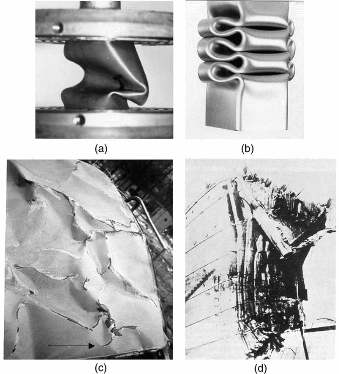
These figures represent a typical example of plastic deformations; diagram (A) represents a folding pattern similar to that of a crushing shell structural component with identical patterns along the zones of impact. The second figure labeled (B) represents a model of superfolding element; a combination of four of this will create a layer of folding within a crushing square column. Figure labeled (C) represents a rare folding phenomenon because of its complex mode of patterns similar to a car crushed roof or a bowed ship. The last representation labeled (d) is a composition of multiple superfolding elements (Mamalis et al. 2003; Tarigopula, et al. 2006).
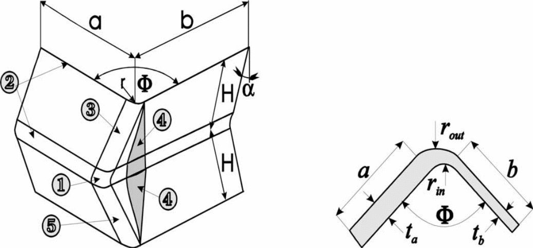
Geometrical similitude is an interesting crushing phenomenon, some engineers observes that a good number of actual folding patterns occurs through assembling of single representative element of the fold. This makes it easy to describe the deformation element from a concept of special macro element known as the superfolding element as shown in the diagrams above (Drazetic et al. 1993; Liu & Day 2006; Nia & Hamedani 2010). This concept helps in describing the geometry as well as its cross sectional dimension.
Equation one
Let one arm of the superfolding element be a and b
Total lenght (C) = a + t
The central angular pattern = ∅
Wall thickness ta of arm of the lenght a
Wall thickness tb of the lenght b
This deformation, which is plastic in orientation, creates five deformation mechanisms. These includes the rolling of deformations, creation of a bend along the stationery hinge line, creation of a deformed floating toroidal surface, deformations bending along hinge lines, along inclination, and locking of traveled hinge lines, and finally conical surfaces opens widely.
Folding mechanism happens through either asymmetrical or symmetrical orientations as shown in the diagrams below. These are typical examples of single superfolding models under the control of switching parameters.
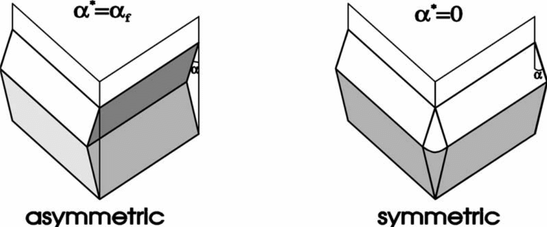
Deformation process is under the control of singular process both in asymmetrical and symmetrical mode. The time like parameter that determines this process must obey the equation below.
Deformation (equation two)
0 ≤ a ≤ af
This equation defines rotational aspects of face sides in the elements, which takes place from the upright posture in the initial stages. In this case, a = 0, a = af = π/2 during the initial folding processes and terminates when this equation comes complete.
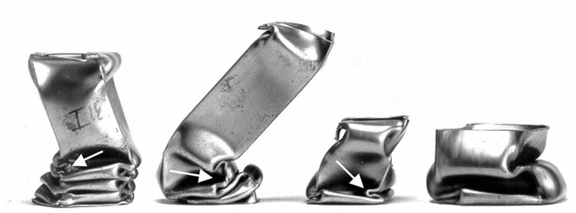
Symmetrical deformation will result in folding as shown below.
Internal energy dissipation rate and the capacity of energy dissipated
Equation three
Internal energy dissipation rate and the capacity of energy dissipated.

Where
S represents shell mid surface
n represents quantity of lines in plastic hinge
Li represents length of hinge
Ø represents rotational rate of jump movement across the hinge line in motion
Kab represents components of curvature rate
Eab represents rates of tensor extension
Mabb and Nab represents components of conjugate stress in a generalized scenario
Taking an example of SE deformation, the above equation makes assumption on a file composed of shells arranged in either toroid or cylinder (axisymmetric) (Toksoy, Guden, 2011; Noels, Stainier & Ponthot 2004). Besides, the equation assumes inextensibility within the hooped direction to give an expansion of a different rate of dissipated internal energy as follows
Equation (4) on different rate of dissipated internal energy
This equation (i) changes to (ii) below
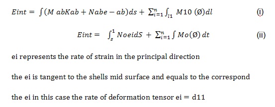
If we integrate equation (ii) with 0≤a≤a1 interval the expansion changes to a single Se energy dissipated as shown below
Equation five

Figures on right side of the above equation defines switching of a, this corresponds to both symmetrical and asymmetrical models when combined.
Equation six
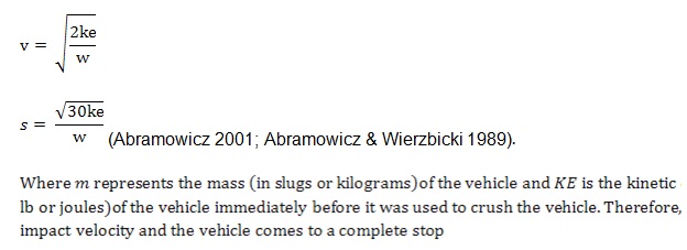
To report on damaged momentum analysis, the first step should involve computation of equivalent barrier speed (EBS). This variable describes the barrier equivalent velocity; the formula below describes its computation process that incorporates determination of energy a vehicle dissipates when a crush occurs (Alexander 1960; Wierzbicki & Abramowicz 1987).
Speed determination
The term equivalent describes the possibility that the speed used may not be ‘actual’; this means that EBS relies on approximation and assumption of speed employed (Toksoy &Guden 2011; Noels, Stainier & Ponthot, 2004). Any effect from post impact velocity gives EBS that is different from the actual speed as shown below.
Choice of Model
Choice of models depends on the type of material required for the thin walled structures, which can either be a solid or plastic FE. Models are the basis for structural analysis. Appropriate models determine structural features and the functions of the structure in design. The main rationale to this innovativeness is the desire to solve problems related to progressive collapse in axial compressed cylindrical tubes. The process involved assumption of kinematic admissive deformation. The main challenge to this method is the assumption on expected observation rather than inclusion of theoretical assumption to the model. With this method it is possible to determine elementary aspects of a crushing process simply by application of relevant formulas. These formulas help in determination of significant properties of crushes as well as deepening the insight of the folding process (Schneider & Jones 2004). This process is however, very important in development of designs that determines a given simulation tool. To effectively elucidate how these processes relates to the entire thin walled structures it is important to use a kinematic approach in determining how crushing mechanism impacts its effects on various design. The application of these calculations in designing a thin walled component is necessary to optimize dissipation of impact energy (Mamalis et al. 2003; Tarigopula et al. 2006).
Geometrical Model
Structural engineering devotes most their time in designing and finding effective methods of creating suitable methods and fail to accord enough time on to actual analysis of the model. The current thin walled models use reduced elements like plate shells, which are however not very effective raising the demand for simulations that use solid elements. Solid types are more adequate than the conventional types. Application of nonlinear to the shell elements is not possible; secondly conventional models are prone to severe modeling errors. A good simulation technique should have a combination of embedded domain and low order elements (Duster et al. 2008; Rank et al. 2011). This technique reduces the need to engage the engineers in preparing model analysis while also presenting accurate and efficient models. These advantages are the basis for recommending a combined model in thin walled structures.
There are three models of thin walled structures with hexahedral mesh. These include single surfaced mesh, the multiple surfaces meshing, and a complex type of meshing. According to Sorger et al. (2012) single surfaced meshing sweeps along the surface referred to as reference surface. A multiple type consists of sets of intersecting solid shells.
Strain-rate Sensitivity
Strain rate influences the crushing behavior in thin walled structures like the columns and beams. Many structural materials of very low-carbon steel, mild like aluminum alloys have stronger strain rate influence than conventional materials. Effective width methodology helps in determination of thin-walled strength. Evaluation of this parameter depends on reduced or effective cross-sectional dimension and the elastic limits of the optimal stress. To solve the problem finite element method combined with analytical designs that employs plastic mechanical approach is appropriate.
Cowper-Symonds formula stated below is effective for determination of strain rate
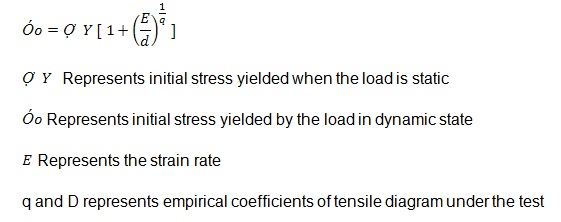
This equation presents a relationship that exists between strain rate and the initial dynamic stress load, however the main shortening arise from its inability to account for the effects from strain hardening phenomenon.
Perzyna et al. (1971) application model is the best method for determining strain rate sensitivity, this model aligns with the Cowper-Symonds method describes previously. However, this model applies the hardening of isotropic strain as well as integration of constitute relationships of repetitive mapping.
The main advantage of this method is therefore the presence of compatible stiff tangents for every step of matrix integration as follows.

Stress and strain Relationship
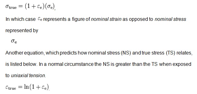
Subjecting a thin-walled structure to tensional or compressive forces results in either elongation of shortening of the material, the poison’s ratio will determine changes in cross-sectional area of the material.
Structural model and loading
The material strain rate has a greater influence on thin-walled crushing behaviors. The capacity to carry a load would increase with an increase of strain rate. However, based on the two methods of analyzing (that is plastic mechanism and the FE analysis) the plastic approach is more susceptible to the effects of strain rate than the FE analysis with regard to column subjected to compressive forces.
Stress and Strain Profile
Stress and strain are directly proportional to one another, an increase in strain results in a constant increase in stress until reaching a certain point called the elastic limit. This limit results in permanent deformation. Applying a high magnitude of force that goes beyond the elastic limit will result in permanent change. This leads to permanent deformation as well; this state sets in because eradication of that load does not change the deformed size or the shape. Force applied before the structure breaks is the ultimate stress while yield stress is the type of stress a structure yields when loaded with a material that makes it go beyond elastic limit This profiling is important to thin walled-structures (Koganti & Caliskan 2001).
Occurrence of Fracture and Deformation
Occurrence of deformation and fractures depends on several factors that determine changes in stress and strain as shown in the diagram below. These factors include object geometry, size of the structure, and forces applied. These factors give rise to a number of fractures and deformations. Between the necking region and strain hardening region the ultimate strength is the transformational factor that determines occurrence of fracture.
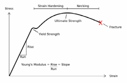
If withdrawal of force happens in case the structure is elastic, the state of deformation will not be permanent because the object regains its previous state of size/shape. Such materials represent a nonlinear elastic deformation that obeys this principle.
σ = Eε
Where σ represents stress applied, ε represents resulting strain while E represents material’s constant figure called Young’s modulus. In Young’s Modulus formula the slope depends on stress and strain.
Deformation process is under the control of singular process both in asymmetrical and symmetrical mode. The time like parameter that determines this process must obey the equation below.
0 ≤ a ≤ af
This equation defines rotational aspects of face sides in the elements, which takes place from the upright posture in the initial stages. In this case, a = 0 during the initial folding processes and terminates when this equation a = af = π/2¹ comes complete.
Fracture is an irreversible deformation type, once the material reaches elastic limit it breaks as shown in the diagram below. The point of fracture is at a level in which application of more forces beyond the ultimate strength level causes irreversible deformation as shown below.
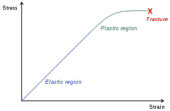
The diagram above shows two major regions a structure undergoes before it fractures namely the elastic region and the plastic region. An increase in strain results in an increase of stress until the structure gets to a point that any additional strain does not increase the stress resulting in fracture. There are very few structures with permanent inelasticity, most structures are either elastic to a lesser or greater limit.
Activation Energy
The equation below represents activation energy computational formula. From a chemical point of view activation energy is the minimal amount of energy acquired by a substance to enable it transform from one form to another.
When a graph of In(K/T) is plotted against 1/T the result is a linear presentation, which gives activation energy.

This energy is important for any material that experiences strain, because it determines its ability to change from form to another.
Fracture mechanisms
Fracture mechanics helps in elucidation of crack propagation of thin walled materials. Analysis of crack propagation depends on solid mechanics analysis. The analysis helps in characterization of fracture resistance. The tool is necessary to improve mechanical performance of the thin walled structure. There are two types of fracture mechanism; these are linear elastic and elastic plastic. To elucidate crack length, estimation of free energy change is the primary stage. This change comes from the deduction process involving elastic (EE) and surfaces energy (SE) (that is SE-EE), however, failure sets in at the point when free energy begins absorption of critical crack length. These changes obey Griffith relationship represented below.

E Represents material’s Young modulus
γ represents density of surface energy
C Represents a constant figure
This formula assumes that E = 62 GPa and γ = 1 J/m2
Behaviour of stress/strain through lobe or ribbon formation
Ribbon formation mechanisms depend on the effects of stress and strain. There are features that characterize a lobe or ribbon formation pattern in a thin walled structural design, for instance a crushing process that involves a plastic crushing component occurs when elasticity process or elastic plastic buckling happens. The main feature that characterizes this process is the localization of deformations plastics in some parts of the structural component. The deposition occurs in some relatively small parts. The localization of plastic deformation takes place in narrow hinged zones or lines (Johnson & Mamalis, 1978; Ohkami et al. 1990), an area that experiences a number of plastic deformations because it is very vulnerable to this problem.
Elasticity and Elastic Limit
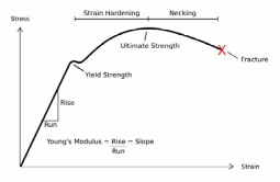
Elasticity of a structure is its ability to regain the original shape and size upon the withdrawal of deformation size. Different materials have different levels of elasticity; while some are more elastic others are less elastic. Elastic limit is the maximum stress that a given structure would exhibit. Applying a high magnitude of force that goes beyond the elastic limit will result in permanent change. This leads to permanent deformation as well; this state sets in because eradication of that load does not change the deformed size or the shape. Force applied before the structure breaks is the ultimate stress while yield stress is the type of stress a structure yields when loaded with a material that makes it go beyond elastic limit. The diagram below represents various stages of elasticity and deformation before reaching a permanent stage beyond which withdrawal of force would not result in the restoration of the original shape.
How Fracture and Deformation Relates to other Characteristics of Materials
Fracture and deformation relates largely with the inherent characteristics of the material exposed to strain. The ease with which a material undergoes deformation before fracturing depends on the type of material it is made up of; irreversible elastic deformation termination of applied forces causes the material to return to its initial shape.
Some materials have strong resistance to strain and therefore the Young’s Modulus formula would slope at a lower gradient than a material with less resistance. Some material would not undergo fracturing while others would experience irreversible deformation resulting in fracture. Those thin-walled structures with larger strain would not reach elastic limits and if they do the force applied would be greatest. Other factors that determine this relationship includes object geometry, size of the structure, and forces applied. These factors give rise to a number of fractures and deformations. Between the necking region and strain hardening region the ultimate strength is the transformational factor that determines occurrence of fracture
Conclusion
Thin walled structures have gone transformation by using different structural models that improves their strength and durability. This is of importance to the passenger in terms of offering protection, several transportation vehicles incorporate structural components with thin walled designs. Their design is accustomed to offer stringent requirements during crush events and therefore making the structure able to sustain abnormal loads. The type of material must however have certain designs with appropriate model choice. Other features that determines structural important includes the elasticity and its elastic limits, deformation property and fracturing ability, and stress/strain relationship.
References
Abramowicz, W 1966, ‘Extremal paths in progressive plasticity’, Int J Impact Engng, vol. 18, no.7/8, pp.753–64.
Abramowicz, W 2001, ‘Macro element method on crashworthiness of vehicles’, in J Ambrosio (ed.), Crashworthiness—energy management and occupant protection, Springer, Wien, New York, pp. 203-302.
Abramowicz, W 2003, ‘Thin-walled structures as impact energy absorbers’, Thin-Walled Structures, vol. 41, pp. 91–107.
Abramowicz, W & Wierzbicki, T 1989, ‘Axial crushing of multi-corner sheet metal columns’, J App Mech, vol. 56, no.1, pp.113–20.
Alexander, JM 1960, ‘An approximate analysis of the collapse of thin cylindrical shells under axial loading Q’, J Mech Appl Math, vol.13, no.1, pp.10–5.
Drazetic, P, Markiewicz, E & Ravalard, Y 1993, ‘Application of Kinematic Models to Compression and Bending in Simplified Crash Calculation’, International Journal of Mechanical Science, vol. 35, no. ¾, pp. 179 – 191.
Duster, A, Parvizian, J, Yang, Z & Rank, E 2008, ‘The finite cell method for three-dimensional problems of solid mechanics’, Computer Methods in Applied Mechanics and Engineering, vol. 197, pp. 3768–3782.
Johnson, W & Mamalis, AG 1978, Crashworthiness of vehicles, Mechanical Engineering Publications Ltd, London.
Koganti, RP & Caliskan, AG 2001, ‘Stochastic applications in crashworthiness’, Proceedings of 2001 ASME International Mechanical Engineering Congress and Exposition, pp. 89-96.
Liu, YC & Day, ML 2006, ‘Simplified Modelling of Thin-Walled Box Section Beam’, International Journal of Crashworthiness, vol. 11, no.3, pp. 263–272.
Mamalis, A, Manolakos, D, Loannidis, M, Kostazos, P & Dimitriou, C 2003, ‘Finite Element Simulation of the Axial Collapse of Metallic Thin-Walled Tubes with Octagonal Cross-Section’, Thin-Walled Structures, vol. 41, pp. 891–900.
Mamalism, AG, Manolakos, DE, Ioannidis, MB, Kostazos, PK & Chirwa, EC 2003, ‘Static and dynamic axial collapse of fibreglass composite thin-walled tubes: finite element modelling of the crush zone’, Environmental Modelling and Assessment, vol. 8, no. 3, pp. 247-54.
Nia, AA & Hamedani, JH 2010, ‘Comparative analysis of energy absorption and deformations of thin walled tubes with various section geometries’, Thin-Walled Structures, vol. 48, no.12, pp. 946-54.
Noels, L, Stainier, L & Ponthot, JP 2004, ‘Combined implicit/explicit algorithms for crashworthiness analysis’, International Journal of Impact Engineering, vol. 30, pp. 1161-77.
Ohkami, Y, Shimamura, M, Takada, K, Tomizawa, H, Motomura, K & Usuda, M 1990, Collapse of thin-walled curved beam with closed-hat section—Part. 1, Study on Collapse Characteristic, SAE paper 900460.
Perzyna, P et al. 1971, ‘Applications of visco {elasticity – in Polish)’, Os-solineum, Wrocaw, Warszawa.
Rank, E, Kollmannsberger, S, Sorger, C & Duster, A 2011, ‘Shell Finite Cell Method: A High Order Fictitious Domain Approach for Thin-Walled Structures’, Computer Methods in Applied Mechanics and Engineering, vol. 200, pp. 3200-3209.
Schneider, F & Jones, N 2004, ‘Impact of thin-walled high-strength steel structural sections. Proceedings of the Institution of Mechanical Engineers, Part D’, Journal of Automobile Engineering, vol. 218, no. 2, pp. 131-58.
Sorger, C, Frischmann, F, Kollmannsberger, S & Rank, E 2012, ‘TUM.GeoFrame: Automated high order hexahedral mesh generation for shell-like structures, in progress’, Computer Methods in Applied Mechanics and Engineering, vol. 230, pp. 200-221.
Tarigopula, V, Langseth, M, Hopperstad, OS & Clausen, AH 2006, ‘Axial crashing of thin walled high-strength steel sections’, International Journal of Impact Engineering, vol. 32, pp. 847-82.
Toksoy, AK & Guden, M 2011, ‘The optimisation of the energy absorption of partially Al foam-filled commercial 1050H14 and 6061T4 Al crash boxes’, International Journal of Crashworthiness, vol.16, no.1, pp. 97-109.
Wierzbicki, T & Abramowicz W 1987, The manual of crashworthiness engineering, Vols. I–IV, Centre for Transportation Studies, MIT, Cambridge, MA.