Introduction
The uninterruptible power supply system (UPS) is a power supply backup technology, which provides emergency energy to a system load when the main power supply system fails (Johnson 3). EATON provides two criteria for understanding UPS (2). It says the UPS “provides backup power when utility power fails, either long enough for critical equipment to shut down gracefully so that no data is lost, or long enough to keep required loads operational until a generator comes online” (EATON 2). In its second definition, EATON says a UPS is a device “that conditions incoming power so that all-too-common sags and surges do not damage sensitive electronic gear” (2).
Institutions and organizations that use sensitive electrical equipment, which is vital to their operations, would ordinarily use the UPS system. For example, hospitals require the UPS to power their electrical equipment because power interruptions could cause injuries or fatalities. Data centers also rely on the UPS for seamless data management, failure to which they would suffer from data corruption, or a loss of information because of system damages (Johnson 3).
An extended analysis of UPS applications shows that different industries use the UPS in power-generation facilities, and petrochemical plants and refineries. The list of UPS users continues to grow yearly. For example, Johnson says, “Recently, other types of industrial companies (pulp and paper mills, steel mills, pharmaceutical manufacturing, and cogeneration facilities) have created a need for UPS by incorporating new technology into their plants to control their processes” (3).
Therefore, different industries use UPS systems for applications that require uninterrupted process controls. This paper recognizes the trend towards the wide-scale adoption of UPS in the global economy and presents a report about the technology. Key tenets of this paper explain UPS applications on power plants by identifying its types, applications, components, and maintenance steps.
UPS Application and Types
UPS Applications
According to Fiorina, UPS systems are only useful in three specific situations (18). The first situation is when a company, or organization, requires an orderly shutdown of its computers. Such an instance is common when computers need an orderly shutdown to save data, or when employees who work in a chemical plant need to know the status of different operating units before undertaking a complete shutdown of machinery (Fiorina 18).
The second situation where a UPS is required is when operations need to continue when a power outage occurs. In such circumstances, the UPS backup technology could have an extensive battery backup system, or share a link to a generator to provide alternative power (Fiorina 18). The third circumstance when Fiorina says organizations require a UPS is when power outages may cause errors in test data (18).
Such data errors could be disastrous and costly for organizations. For example, if a computer reads data as 2,000 instead of 2.000, it may cause serious operational problems in an organization. Similarly, if a distributed control system that controls a volatile refinery process experiences such as data hitches, it may have serious implications throughout the organization’s processes.
There are different types of end-user UPS applications. Many UPS systems have important UPS features, such as battery check and automatic inverter check, which increase the system’s usability and help improve its repair and maintenance processes (EATON 1-5). Although repairing and maintaining UPS systems could be costly, Johnson says that choosing the right UPS technology could help reduce these costs (3).
Types of UPS Systems
There are different types of UPS systems, which range in size and functionality (depending on their intended use). For example, UPS systems that should protect a single computer could range in size and functionality from those that should protect large data centers, or buildings (Townsend 5). The largest UPS in the world can backup power for entire cities. For example, the 46-megawatt Battery Electric Storage System in Fairbanks, Alaska, could provide a backup power supply to the entire city and its environs. A deeper analysis of UPS typologies reveals that there are three major operation types described below
Single Conversion Systems for Normal Operations
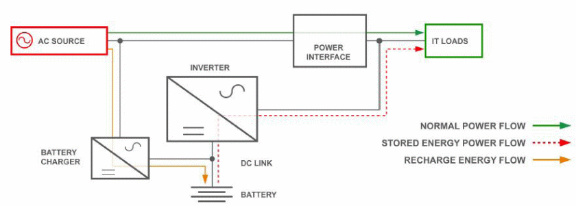
The single conversion system often works in normal operations when AC power connects directly to the equipment. However, when there are power fluctuations in the system, the UPS uses an inverter to draw power from the batteries (DC) and stabilize the power system. It also disconnects the AC power to prevent the inverter from facilitating a backflow of power to the utility (Integrated Publishing 1).
The AC connection would only work again after the battery depletes its power. The AC connection could also reactivate when there is a restoration of the primary power source. The standby and line-interactive connections are the main types of single conversion designs associated with this type of connection.
As its name suggests, the standby design allows the utility to use AC power, until the UPS detects a problem and engages the use of DC (backup power). Limited power conditioning could also occur in such systems when designers use transformers in the system design (Integrated Publishing 3). Comparatively, the line-interactive system often uses a regulatory mechanism that checks the power input before allowing it to be available for use by a utility system.
However, this system shares similarities with the standby system, in the sense that both of them rely on the battery to manage power fluctuations (EATON 3). The internal design of a line-interactive UPS appears below:
Double Conversion Systems (By-Pass Transformer)
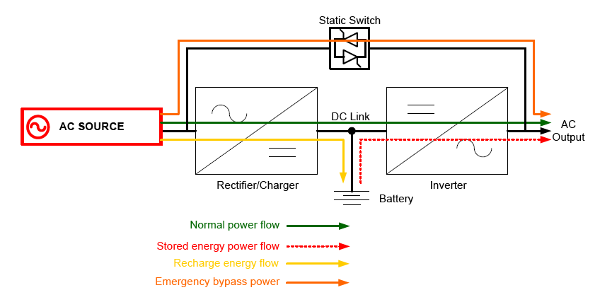
As its name suggests, the double conversion system often involves the double conversion of power. The first step involves the conversion of AC power into DC power, which later connects to an output converter (EATON 3). The second phase of the power conversion involves the conversion of DC power back to AC power before its use in the utility system (Fiorina 18). The main purpose of the conversion system is to isolate critical loads from raw utility power.
This way, the utility system would only experience clean and raw utility power. Normal operations would dictate that double power conversion occurs continuously. In the event of a power outage, or a power fluctuation, there would be a shutdown of the input converter. Thereafter, the power would come from the battery for use in the utility system. The battery power would be the main source of energy in this regard until there is a normalization of the AC power input.
A failure of the rectifier, or inverter, which converts AC to DC power, would mean the establishment of a bypass path to support the output loads (Fiorina 20). The diagram below shows the internal design of a double-conversion UPS:
Multi-mode Systems
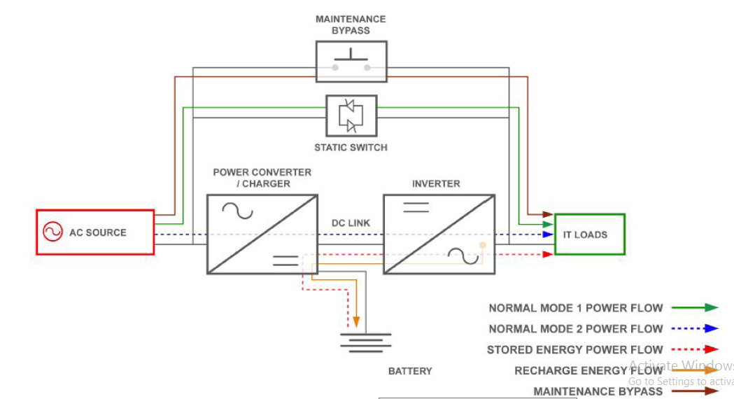
The multi-mode system is a combination of both the singular and double conversion systems. Designers choose to use both methods because they improve the efficiency and reliability of the system. EATON says, “Under normal conditions, the system operates in line-interactive mode, saving energy and money while also keeping voltage within safe tolerances and resolving common anomalies found in utility power” (4).
Efficiency and reliability would also occur when the system automatically switches to double-conversion mode when there is a power fluctuation, or when there is a fluctuation in the AC output. This process completely isolates the AC power from the utility system. Efficiency and reliability also emerge when the AC power falls outside the predetermined limits of the double conversion system, as the battery system would start to provide alternative power.
When the generator starts, the UPS would engage the double conversion mode until there are no more fluctuations on the AC power (EATON 4). The high efficiency and line-interactive mode would thereafter set in when the system stabilizes.
The multi-mode UPS system is unique because it strives to strike a balance between efficiency and protection. When the system is under normal conditions, maximum efficiency would emerge. However, when these conditions are not ideal, some level of efficiency diminishes for the sake of protection (EATON 4). Such a trade-off could yield significant cost savings for organizations. For example, different data centers could save tens of thousands of dollars, on energy savings, without affecting the quality of the data management services. The internal design of a multi-mode UPS system appears below:
A simple comparison of the single conversion and double conversion system reveals that the single conversion phase is more efficient than the double conversion system, but it offers less protection compared to the latter. This criterion is a good indicator of consumers who may not know what to choose between the two. In other words, they need to choose between efficiency and protection as the main predetermining factors in their choice of UPS.
Nonetheless, according to Johnson, multi-mode systems could provide the best balance between the two (4). Using this analogy, he says this system is more suitable for companies, or organizations, that want to achieve a perfect blend of the two (Johnson 4). Besides the three classifications of UPSs mentioned above, other researchers have used online and offline classification systems to define UPSs.
Online and Offline Classifications
Mainly, the UPS systems work by converting some of the AC power to DC power for storage. Whenever systems need power, the conversion occurs again, where DC power changes back to AC power. The inverter operation explains why the UPS system could be offline or online. Offline UPS systems are less costly and easier to maintain compared to online UPS systems because the inverter is usually offline.
However, they are less effective to use because when transferring power from the main power source to the battery, power interruption occurs for a few milliseconds (EATON 4). Most modern equipment could easily sustain this power variation, but older ones cannot, and may shut down during the power transfer. An online UPS system uses a different technology and is more effective because the inverter is always active and transfers power to the load. Therefore, whether the main power is active, or not, there is a constant supply of power. This constant supply of power comes from the power stored in batteries.
Charger and Battery (Its circuits and their components)
The battery types used in UPS systems depend on the type and size of the batteries. Spears adds that the rate of discharge associated with these batteries also defines the types of batteries used in UPS systems (5). Peukert’s law defines the characteristics of these batteries, in detail, by demonstrating that a battery’s capacity is a function of its discharge rate and its “life-expectancy” (Spears 4-5).
Packaged UPS system batteries have run-in times that most users could use to estimate their total life expectancy. Estimating the run-times for small batteries is easy because they require simple computational methods of doing so. However, large batteries that could power buildings, or big data centers, require complex mathematical algorithms to estimate their run-times.
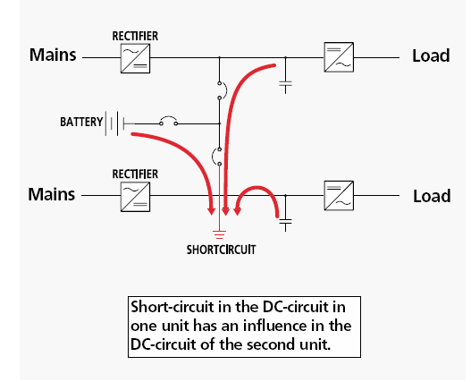
In terms of battery configurations in the UPS, the EEP says, “For Parallel / Redundant and Full Dual UPS system configurations, where two and more units are combined, a common battery configuration is possible” (15).
While one side of this analogy would show how the battery configuration, described here, would yield cost and space advantages, the EEP says the same areas of competency could be potential areas of weakness (15). For example, the failure of one DC unit could affect all other DC units in the system. Common batteries would have the type of configuration described below:
A critical analysis of the circuits appears below:
Circuits
The basic circuit diagram for a typical UPS system appears below:
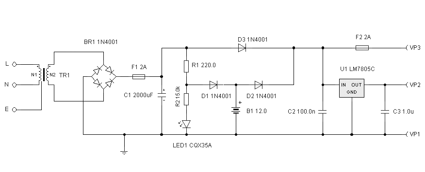
The circuit diagram described above could work in a typical UPS industrial UPS. The diagram shows that the batteries provide power during a power outage. It also does so when there are variations beyond the normal limits of the voltage line. This way, they prevent a disruption of the operating system and provide a steady and regulated power output. This power output is usually 5 Volts by LM7805 (Curtis 234).
An unregulated supply would ordinarily be 12 volts. The primary winding of the transformer would have a power input of 240V, while the secondary winding could have up to 15 volts (Curtis 234). However, this outcome could only happen if the value is set at 12 volts running 2amp. FS1 would act as a circuit breaker to protect equipment against short circuits (Curtis 234). It could also protect the entire system from a battery cell malfunction.
Referencing the above diagram, we find that the presence of electricity would cause LED 1 to light up. However, the presence of light at the LED would only happen if there were a power outage, setting the stage for the battery to take over the power supply in the entire system.
Using different regulators and batteries would offer more flexibility to the system. For example, EATON says, “utilizing two 12 Volt batteries in series and a positive input 7815 regulator, can control a 15V supply” (3). A general industrial UPS system would also adopt the same principle. Such systems split into three categories:
- Standby (battery backup and surge protection)
- Line Interactive Systems that have valve voltage transformers and regulate voltage variations in the AC
- Online systems which supply, or partially supply, the power
Other components of the battery appear below:
Diodes
Diodes are important components of the UPS battery because they allow the flow of power from one direction and prevent an alternative flow of power from another direction. Diodes are applicable in different contexts. However, in the context of the UPS system, they are applicable in rectifier circuits.
Static Switch
The main purpose of a static switch is to provide an alternate source of power to a backup source in case a UPS output malfunctions. Based on this purpose, static switches often have overflow circuits (Curtis 234).
Capacitors
The main purpose of capacitors in the UPS system is to smooth out voltage fluctuations (Spears 1). A typical UPS system would have more than a dozen capacitors. They are usually in different sizes because small ones even out the voltage supplied to UPS processors, while large ones regulate the power flowing to the equipment (Curtis 234).
Ripples on the AC
Given the importance of batteries to UPS systems, many UPS users are concerned about the negative effects of internally generated heat on battery life and performance (Emerson Network Power 1). This concern stems from the fact that high temperatures adversely affect battery life. Critical power engineering consultants are more concerned about the ability of some UPS systems to generate ripple currents that exceed the recommended levels (Emerson Network Power 1).
However, independent research studies show that if these ripple currents are not excessive (three or four times above the recommended level), there is no cause for concern (Townsend 6). The statistical expected life of a battery is also likely to have minimal effects.
Many people hold a misconception that the rectifier is the main source of AC ripple currents (Emerson Network Power 1). However, the DC inductor prevents such an action from occurring because, through its filter, it blocks the currents. Therefore, unless there is a missing drive signal in the rectifier, the ripples would not occur.
According to Townsend, most UPS systems have the rectifier output, inverter input, the DC filter, and the battery interconnected. The main purpose of the rectifier is to convert the AC power to DC power (6). The latter often passes through the DC filter, which consists of different inductances that have parallel capacitors. The DC power that goes through the filter primarily powers the batteries. It also supplies the input of the inverter with power.
The inverter carries out a primary task of converting the DC power back to AC power, thereby making it useful for devices that have a high power requirement, such as computers and its peripheral equipment. The DC, its filter, and the battery share an AC ripple because they align in a parallel arrangement. The inverse of the ratio of the two would determine the power-sharing ratio between the two AC impedances (Townsend 6). Stated differently, the lower AC impendence will conduct the highest current. In many older UPS systems, the DC capacitors had lower AC impedance, compared to the batteries. A shift in this differential has emerged from design changes.
Harmonics on the DC
Harmonic tests often involve checking a UPC’s input and output mechanics during the steady load tests. Ordinarily, engineers test the harmonics at 0%, 50%, and 100% loads (Integrated Publishing 1). These tests allow them to determine the effectiveness of the inputs and output filters. Here, it is important to point out that most manufacturers design the UPS system to have the highest efficiency when the load is heaviest.
Therefore, the biggest harmonic distortion happens when there is the least load. Conversely, it evens out as the load increases. Nonetheless, as the Integrated Publishing points out, there is no cause for alarm if there is a consistent distortion across modules and phases (3). A total harmonic distortion could only occur if there are deviations from perfect sinusoidal waves. A UPS system that has a high harmonic distortion requires a high maintenance budget compared to that which has a low maintenance budget.
Heat generation is an outcome that symbolizes wasted energy in inefficient UPS systems. However, Fiorina says there is minimal damage to conduction components if a UPS with high distortion levels has a low load (18). This is because the unit would produce enough energy to sustain the load through the excess heat. Based on the above analogy, the Emerson Network Power recommends that experts should test the harmonics at different levels that include input voltage and output voltage (1).
Experts should do other harmonic tests to test input currents and output currents. Since thyristor rectifiers could cause harmonic disturbances, they could easily affect the power factors of the UPS installation. Fiorina says such levels of pollutions are acceptable, subject to certain factors (18). The first one is the UPS should have a low power rating compared to the short-circuit power rating associated with the entire network (Fiorina 18).
When there is a disturbance and the voltage distortion rate surpasses the acceptable limits, users should take corrective action. The most common solution to this problem is inserting a series of inductance in the system (Emerson Network Power 1). Harmonic decoupling is achieved in this manner. If this measure is insufficient, users could use phase-staggered rectifiers to reduce the number of disturbances. Years of adopting such recommendations have increased people’s mastery of the process.
Similarly, they have contributed to its wide adoption. Researchers say that, in the future, changes in operational standards and the increase of polluting equipment would lead to the increased use of clean rectifiers (Fiorina 18). Single-phase equipment is already using these rectifiers. The sinusoidal technique is also a product of this trend (Fiorina 18).
Silicon-Controlled Rectifiers (SCR) on the Converter
The silicon-controlled rectifier (SCR) is a type of semiconductor. It is mainly comprised of transistors and diodes (Integrated Publishing 1). A schematic representation of the SCR appears below
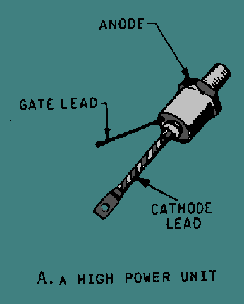
Most high-power units have SCRs that resemble the above diagram. Although SCRs mostly comprise of transistors and diodes, they should not be confused to be either one of those. Although the use of the SCRs may improve the efficiency of transistors and rectifier diodes, the basic function of the SCR is to switch on, or off, high voltage power. It can do so without having moving parts, which may need replacement. The diagram below represents a double conversion bypass of a UPS module that uses the SCR switch.
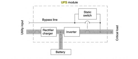
The removal of the SCR gate by itself would not ordinarily turn off an SCR. One of the major challenges of UPS inverter designers was to the time of the SCR switch. Auxiliary commutation was one way for the designers to turn off the SCR switch (Curtis 232). This method uses stored energy in a bank of capacitors. To turn off the SCR, the stored energy connects back feed into the SCR. This step reverses the current flow to reach a zero crossing.
Forces or auxiliary commutation often results in blown fuses (Curtis 232). Nonetheless, inverter designs often have made SCRs obsolete. They commonly occur in modern high-power transistors. However, larger capacity UPS models still rely on the SCR because they help with the improved functionality of the rectifiers and battery charger portions of the system.
Since AC power naturally reserves itself at 120 times per second, Curtis says SCRs often act as cost-effective conversion devices of AC power to DC power (232). However, its use is still problematic for engineers who want to integrate it into the overall mission-critical power infrastructure (Integrated Publishing 2-3). Specifically, this problem emerges when they want to realize harmonic, or generator, compatibility.
SCRs are useful because of the heavy power load seen, or required, in today’s hospitals, buildings, and other facilities that are important in service delivery. Variable speed drives and inferior UPS systems cannot provide the high-quality power required by such facilities. Their inefficiency comes from their inability to provide consistent line current and voltage (Integrated Publishing 2-3). Utility power could manage some of these weaknesses, but systems that rely on standby generators cannot. This outcome is true if there is wrong design.
Some non-linear load problems also arise from the presence of silicon-controlled rectifiers on converters (the converters convert AC power to DC power). The SCR mostly affects the formation of the sine wave (Curtis 232). High levels of distortion could easily affect the voltage output and the frequency regulation indices. In this regard, there would be variations in the Genset engine speed as it tries to find the right RPM for optimum performance (Curtis 232).
Connected loads could suffer from this adjustment because of possible line disturbances. The same outcome could also yield excessive heat from the generators, thereby creating excessive heat in the SCR. Some of the possible solutions touted for addressing the above problems include using non-rotary UPS or Mitsubishi 5th-Gen IGBT UP (Curtis 232). Proponents of the products prefer their use because of their minimal influence on the sine wave formation. Furthermore, they allow for a Genset size that is equal to the UPS rating (Integrated Publishing 2-3).
The UPS Maintenance Steps
Maintaining the UPS system is important for the proper functioning of the system. Stated differently, it keeps it in good working order and reduces the chances of failure. A holistic UPS maintenance plan should consider important features of the UPS, such as its age and its expected lifespan. Such information may also help users to budget for replacement parts. According to Johnson, a maintenance strategy should also include an organization’s future, as well as its objectives and mission (3).
This way, users would be able to establish important information about the business, such as what point of growth, or decline, is the business operating in and the resilience of the business to adversities. The main purpose of doing so is to prioritize which equipments require urgent maintenance and which ones do not. Similarly, such information would be important in determining the level of service to offer in the maintenance process. Typically, the process of maintaining UPS systems consists of preventive and corrective maintenance procedures. Preventive maintenance often includes check listing a series of issues about how the UPS system works. Comparatively, corrective maintenance procedures are applicable because of failures in the system.
Generally, electronic components of the UPS system are not subject to severe wear and tear as electromagnetic components of the same system. Therefore, the latter often requires systematic maintenance. It is difficult to have a standard maintenance procedure for all types of UPS systems. Therefore, users should endeavor to use the manufacturer’s maintenance guide to understand the specific maintenance requirements and troubleshoot diagnostic guidelines.
Overall, routine maintenance of the UPS reduces the probability of a complete failure of the system. Fiorina says such maintenance procedures are important because they reduce the probability of load loss events (18). The systematic inspection would make sure that the electronic and mechanical components of the system are in good working condition. Failure to do so could lead to a system malfunction because critical components of the system, such as batteries and capacitors, would wear out after some time. The identification of such issues could easily happen by developing a solid maintenance plan. An effective preventive maintenance plan would include the following issues:
- An annual scheduled preventive maintenance plan for the electrical systems and its batteries.
- A rapid emergency response plan to reach a trained technician who would offer help on specific UPS models.
- Access to technical support and design engineering resources.
- Remote monitoring that has an alarm notification and a rapid response linkage of technicians.
- Adhering to maintenance routines for removable and replaceable parts (this step is more important for replacing components that easily wear out, such as batteries and capacitors).
- A proper understanding of the UPS lifecycle, including possible expansion features and total ownership costs.
- Maintenance of accurate records
Maintaining Batteries
Batteries are easily prone to wear and tear. Therefore, Townsend (6) proposes the importance of replacing them every two or three years. Users should observe this routine because the failure of one battery could cause a failure of the entire UPS system. This is why, in this paper, we have identified battery replacement as a key part of the maintenance plan. Many users today employ new technology to check the performance of their batteries.
For example, some companies use a battery monitoring system to know when a battery’s performance is outside the factory specifications (Townsend 6). This development comes from studies, which have shown that self-monitoring systems are faulty because of errors in misrepresentation (Townsend 6). Lastly, according to the EEP, the UPS maintenance checklist should have a part in checking regular equipment testing (15). A schedule for regular equipment testing could occur quarterly, semi-annually, annually, or biannually. The tests may include checking for liquid contamination from batteries and capacitors, visually checking equipment for loose connections, conducting thermal scans on electrical connections, and cleaning, or vacuuming UPS equipment enclosures.
UPS Troubleshooting note
The maintenance and troubleshooting of uninterruptible power supply systems and batteries could span several key areas of operation. They include power quality issues and improvement measures, power planning for continuity, UPS systems alternatives, solid-state devices and rectifiers, rectifiers and inverters, static UPS systems, battery-charging mechanisms, sizing of batteries for DC and UPS systems, and the maintenance and disposal of batteries (EEP 3).
Some of the issues for troubleshooting power quality issues include voltage variations, interruptions in supply, surges, and noise, presence of harmonics, and frequency disturbances (EEP 3). However, for purposes of this analysis, we identify seven main problems associated with UPS use and their possible remedies. They appear below
Power Inverter fails to turn on
The possible causes of the failure of the power inverter to turn on are the defective power switch, tripped UPS/inverter, the poor connection of batteries, loose battery terminals, corroded, or rusty, battery terminals, weak battery, discharged batteries, reversed terminals of the batteries, or faulty batteries (EEP 3).
The battery is not Charging
Some possible causes of the failure of batteries to charge include a dead battery, burnt rectifiers, melted fuses, or loose battery connections. Some of the possible remedies would be replacing the battery, taking UPS inverter to a service center for repair, replacing melted fuses, and cleaning corroded battery terminals (EEP 4-5).
Shortened backup Time
Some possible causes of this problem include excessive power consumption, worn-out batteries, improper battery charging, and loss of electrolytes in batteries. Some of the possible remedies for these problems include disconnecting the extra load, changing the battery, fixing UPS inverter, and topping up the flooded lead-acid battery with distilled water regularly (EEP 4-5).
UPS/Power Inverter works only in Inverter Mode
Some possible causes of this problem include failure to connect the input, melted fuse, effective input protector, the input is too high to be accepted, and input is too low to be accepted. To remedy these problems, users should check power cable, change melted fuses, rest input protectors, and check the input voltage to remedy the last two problems (EEP 5).
Alarm Buzzer Beeps Continuously
The main causes of the alarm buzzer beeping continuously include overloading the system, stuck cooling fan, and wrongly connected battery terminals. To remedy these problems, users should disconnect the extra load, service the UPS/inverter, and correctly connect battery terminals (refer to the user guide).
LCD Displays Faulty Code
The possible causes of a faulty LCD could emerge from an internal, or external, discrepancy in the working of the machine. If it is an internal problem, the UPS/inverter needs repair. Conversely, if it were an external problem, checking battery cable connections and the input, or output, wires would solve the problem (Johnson 4).
Noise Coming from UPS/Power Inverter
A noise coming from the UPS power inverter could be because of a noisy fan, presence of strong winds, or a humming noise caused by an impure sine wave formation. Cleaning the fan could take care of the noisy fan. However, it is difficult to remedy the other two causes because they are normal.
Conclusion
Based on the insights highlighted in this paper, we find that there is growing adoption of UPSs in today’s globalized world because of increased reliance on electrical power and the increased importance of protecting sensitive equipment in the workplace. Generally, different industries use the UPS system to protect their hardware. The effective and reliable functioning of computers, data centers, and telecommunication networks mostly depend on UPS technology because power interruptions could cause damage to equipment or service provision standards in utility centers. Small manufacturing companies have spurred most of the trend towards the adoption of UPS technology.
Companies that use automated, or integrated, manufacturing facilities are mostly driving this trend because they often rely on local area networks that require a stable power connection to function well. However, the effective adoption of UPSs depends on the effective understanding of UPS basics as highlighted in this report.
Works Cited
Curtis, Peter. Maintaining Mission Critical Systems in a 24/7 Environment, London, UK: John Wiley & Sons, 2011. Print.
EATON. UPS Basics. 2009. Web.
EEP. Maintenance for UPS systems. 2010. Web.
Emerson Network Power. Effects of AC Ripple Current on VRLA Battery Life. 2009. Web.
Fiorina, Jean. Harmonics Upstream Of Rectifiers in UPS. 2016. Web.
Integrated Publishing. Silicon Controlled Rectifier (SCR). 2014. Web.
Johnson, David. When, Where and How To Apply UPS, Columbus, OH: Solidstate Controls, Inc.
Spears, Ed. Straight talk about capacitors in your UPS. 2016. Web.
Townsend , Mark. AC Ripple Currents in UPS DC Link. 2015. Web.