Literature Review
This section focuses on the review of literature on servo motors and DC motors, in general as well as in the context of the current research project. The chapter begins with the introduction of servo and DC motors, followed by their usage in the current study. Lastly, the chapter ends with a conclusion of the use of Servo and DC motors in the current work.
Introduction
Servo motors and DC motors
Motors have been by far one of the most crucial components across the factory front. Being the largest consumers of power, the accuracy in motor control is the easiest measure of minimizing energy consumption. Electric motors are generally categorized in terms of their functions as servo meters, gear motors, and so on, as well as by their electrical specifications as Alternating current (AC) and Direct current (DC) motors. While DC motors are given more preference mainly in the variable seed applications, increasing use of AC motors is seen before enhancements in solid-state elements.
In this context, the servo motor is a mechanism that is aimed at positioning and controlling speed in the systems called closed-loop control. The current project makes use of a servo meter to turn over a wide range of speed instructions obtained from the computer. In general, DC and AC servo meters are primarily found in applications depending on their machine structure. DC servo motors have been applied in computers, robotics, numerical control machines, industrial components, speed control of vehicles and alternators, control mechanism purposes, and so forth. Further, the field of control of mechanical linkages as well as robots sees the most potential use and research works of DC motors.
On the other hand, servo motors are extensively equipped for applications relating to radio-controlled models, such as cars, planes, robotics, test equipment, industrial automation, etc. Although a servo is not easily defined nor is self-explanatory as its mechanism does not apply to any particular device or machine. Typically, it is a term that applies to a task or a function.
Any electric motor works on the principle of electromagnetism, as aforesaid. Any conductor that carries current creates a cloud of the uniform magnetic field. This conductor is directed at experiencing a magnetic force when it is subjected to an external magnetic field. It should be mentioned that its strength is totally dependent on the current across the conductor, as well as the magnetic power of the field. The inner composition of a simple DC motor is so designed in order to facilitate harnessing of the magnetic interaction taking place between the conductor and an outside magnetic field for developing uniform rotational motion.
DC motors are broadly utilized in robotics due to their smaller size and greater energy output. Experts suggest that DC motors, by far, have been a better option for generating power for wheels of a robotic car as well as for other similar mechanical constructions.
DC motor speeds are easily varied hence they are commonly used in applications where there are speed control, servo control, as well as for positioning needs. A servo motor can be either AC or DC, and typically constitutes the drive section and the encoder. Moreover, a servo motor operates more smoothly relative to a stepper motor. It also has a much greater resolution with respect to position control.
Essentially, if the work is considered to be the control variable, servo motors are used in closed loop control systems. As shown in the schematic below, the digital servo controller dictates working of the servo motor by transmitting velocity command pulses to the amplifier that is responsible for driving the servo motor.
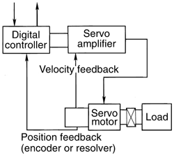
With this, essential feedback devices such as resolver, tachometer or encoder are either integrated in the servo motor or are placed in isolation, mainly on the external load. A major benefit of this setting is that it offers the exact position of the servo motor as well as its speed feedback compared by the controller to its coded motion profile and utilizes it for modifying its speed signal. Furthermore, servo motors are characterized by a motion profile, which is nothing but a set of instructions loaded within the controller that configures the servo motor working with respect to time period, its position and speed. Indeed, servo motor’s ability to become compatible with the dissimilarities occurring between the motion profile and feedback pulses greatly relies on the kind of controls as well as servo motors utilized.
Working of Servo motors
Servo motors fall under a special class of motors mainly designed for applications that involve position control, torque and velocity control. These motors specialize in techniques such as lowering mechanical time constant, lowering electrical time constant, generating permanent magnetic force of high flux density for generating the field, and support of fail-safe electro-mechanical brakes. Furthermore, for application where the load often needs to be speedily accelerated or decelerated, the motor’s mechanical and electrical time constants plays a pivotal role. In such cases, the mechanical time constants are decreased by reducing the rotor inertia.
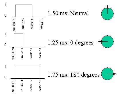
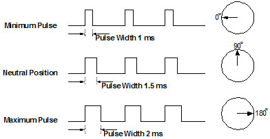
Therefore, the rotor of such motors generally has an elongated body. Moreover, servos are controlled my transmitting them a pulse having variable width, as shown in the following schematic. As a servo is equipped with an output shaft, a coded signal is used to position it to certain angular position. The servo motor and its shaft put on special angular position depends on the coded pulse greatly. As and when there is a change in the coded pulse, a similar change is detected in the angle at which the shaft is positioned. Practically, servos are seen in radio controlled cars, and robots in particular. Basically, the motors are of very small size and are usually built inside a control circuitry; however, regardless of their size, these motors provide output of tremendous power compared to the size. Hence, it can be noted that a less loaded servo motor does not use up much energy.
The following schematic presents the control circuitry, the motor, set of gears and the holding case. Also, 3 wires can be seen that are used for power, ground and control.
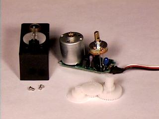
Typically, the parameters included in the coded signal are :
- minimum pulse;
- maximum pulse;
- a repetition rate.
For a given rotation constraint provided by a servo, a neutral position is one at which the servo potentially rotates in equal modulations in the clockwise as well as in the anticlockwise direction. Here, in this context different servos are associated with different constraints across each rotation. Nonetheless, they all fall in the neutral position said to take place at approximately 1.5 milliseconds.
The servo motor is made up of a control circuitry and a potentiometer, both connected the shaft or output device. This potentiometer is responsible for enabling the control circuitry to read and control the changing angular positions of the servo meter. When the shaft is positioned at the accurate angle the motors stops operating. In case the control circuitry detects that the angle is incorrect, it will position the motor in the accurate angle or direction. Furthermore, the output shaft of the servo motor is able to travel somewhere close to 180 degrees. Depending upon the manufacturer, the motion of the output shaft can be around 210 degrees.
Furthermore, a simple servo motor can be used to determine any angular motion which may usually range from 0 to 180 degrees. In addition, it is unable to mechanically move any beyond this position because of a “stop” that is mounted on top of the primary output gear. In essence, the amount of power given to the motor is directly dependent on the distance it needs to move. Hence, if the shaft tries to turn a larger distance the motor will operate at its maximum speed. However, if it needs to change the position by a smaller angle, the motor operates at a relatively slower speed. This phenomenon is known as proportional control.
Furthermore, the control wire is used for communicating the angular position at which servo motor is required to turn. This angle depends on pulse code modulation or pulse width modulation (PWD), which is the duration or modulation of a pulse which is applied to the control wire. As the servo anticipates seeing a pulse for every.02 seconds, the length of the pulse determines the extent to which the motor has turned.
For instance, a pulse having duration of 1.5 milliseconds is likely to make the motor change its position to a complete 90 degree position. This is typically known as neutral position, as aforementioned. Nevertheless, in case the pulse is lesser than 1.5 milliseconds, the motor is likely to turn the shaft to near 0 degrees. And if the pulse has duration greater than 1.5 milliseconds, then the shaft turns to a position much closer to 180 degrees, as mentioned previously. As depicted in the diagram below, one can observe that the duration of the pulse that dictates the angular position of the output shaft is indicated by the green circle with an arrow attached to it.
Working of a DC motor
A DC motor is comprised of 6 fundamental components, namely, axle, rotor, stator, field magnets, brushes and commutator. Most commonly, the external magnetic field in generated in DC motors by high intensity permanent magnets. As shown in the schematic, the stator forms the stationary part of the motor which holds the motor causing and two or more permanent magnetic poles. The stator is responsible for determining the rotation of the rotor along with the axle and the connected commutator. In addition, the rotor is made up of windings or a core, which are electrically attached to the commutator.
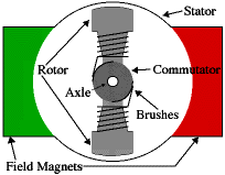
Furthermore, the geometrical arrangement of the brushes, commutator points, and the rotor armature is such that on application of power, the polarities of the core and the stator magnets will become misaligned. This in turn will enable the rotor to rotate only when it is closely aligned to the field magnets of the stator. Once the rotor is accurately aligned, the brushes will move to the next commutator points and charge the next windings, and so on.
A two-pole motor is an excellent example where the rotation alters the flow of the current to pass in the opposite direction across the rotor winding, thereby flipping the magnetic field of the rotor. This eventually produces continuous rotations. However, practically, DC motors always have poles greater than two. This is commonly chosen so in order to eliminate the creation of “dead spots” within the commutator.
There is no better way to view how a simple DC motor is integrated by various components, than by simply opening it up. However, this being a cumbersome job requires the destruction of a good motor. The following diagram represents the interior components of a disassembled DC motor. This motor is a basic DC motor having 3 poles, together with 2 brushes and 3 commutator points. It shows the use of iron core windings which have several benefits.
Firstly, the iron core offers a powerful, rigid support for the armature and is particularly a crucial consideration for higher-torque motors. Also, the core pushes heat far from the rotor windings thereby enabling the motor to be operated at much greater efficiency and speed. Iron construction is also inexpensive in comparison to other forms of construction. However, iron core construction is also associated with several drawbacks. The iron winding has a comparatively greater inertia which tends to restrict motor acceleration. In addition, this mechanism leads to high inductances in rotor windings. This disadvantage tends to restrict the brush as well as commutator existence.
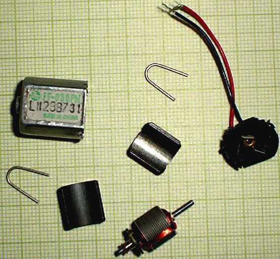
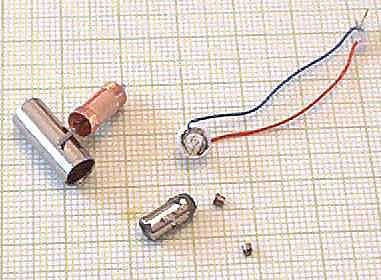
In smaller DC motors, an alternative design is used which is characterized by a “coreless” winding. Structural integrity is obtained through this design as it is highly reliant on the coil wire itself. Therefore, the windings tend to get hollow which calls for placing of the field magnet within the rotor coil. Additionally, coreless DC motors are associated with lesser degree of armature inductance as compared to iron core DC motors having more or less same size, extending brushes and commutator life span.
In essence, the coreless design enables manufacturers to produce smaller motors; because of the shortage of iron in their rotors, coreless motors are sensitive to overheating. Therefore, this design is usually used only smaller, low-power DC motors. Again, the inner components of a coreless motor can be said to be instructive, as shown in the figure below.
Brushless motors are said to resemble AC motors which also works to generate rotor motion with the help of a moving magnetic field. This can be stated as a sole reason as to why the brushless motors is usually referred to as AC brushless or DC brushless depending on the type of operation of the motor. Interestingly, major applications of brushless DC motors are seen in hard disk as well as a wide array of industrial sectors. Moreover, a brushless DC motor comprises of a rotor in the form of a permanent magnet. Again, such type of a motor features most of the properties as well as laws that are primarily equipped in a DC machine.
Conclusion
A DC motor uses a commutator built upon the shaft which automatically changes the polarity of the armature winding when the shaft rotates. This switching keeps the magnetic fields between the armature and stator in such a state that allows for continuous rotation or the armature. Without commutation the motor shaft would rotate only until the magnetic fields lined up North to South at which time the motor would stop turning. On the other hand, a Servo motor does not make use of a commutator. Instead multiple sets of field windings are located about the stator. A single pair of these field windings is energized at a time.
The shaft rotates into alignment with the energized field and stops movement. In order to make a servo motor turn the fields are energized in turn (STEPS) to make a rotating field. The armature then follows this rotating field. In essence the “Commutation” or switching On/Off of the field coils is done electronically. This can be done with a driver circuit of a micro controller. The advantage of a servo motor is precise rotational control which is based upon the number of steps/rev and any associated gearing. Very precise movements can be performed as attested to by their use in hard drives and automation.
Likewise, DC motors provide torque. A high torque DC motor like a car starter is series wound. Other DC motors like shunt wound are used in automation. The advantage with the use of a DC motor is easy speed control by easily varying the voltage applied to the motor. Rotational control of either may be done with some form of feedback. The feedback is used as a signal to a motor controller which will stop the rotation of the shaft with the help of a control of the particular motor in use.
One may also consider using the same motor you currently have and consider providing some means to control the motor controller which drives the motor, such as 4-20 ma input to a motor controller which is designed to drive either a DC motor or Servo motor. Only the existing motor and the mechanical setup need to be retained while the existing manual motor controller can be changed to a type that will interface to your application.
Servo motors are extensively used in the field of robotics. It should be mentioned that the size of servos is small. Nevertheless, this ;does not prevent them to show extreme power. Controlled by an in-built circuitry, a servo motor model Futuba S-48 has been exceptionally used as a standard servo for building robotic machineries. As aforementioned, a servo motor derives power in proportion to the applied load. The power may be derived to the mechanical load.
Known for their energy conversion mechanisms, servo motors are made up of a set of tools. These tools are of two kinds, a control circuitry and a case covering to hold these equipments. One can state that the working mechanism of servos is very easy. The shaft or the output device connects the control circuitry within the servo, and the potentiometer. The angular position of this shaft is controlled by the pot by using the coded pulses coming from the control circuitry. In addition, the shaft is positioned between angles o and 180 degrees, typically.
References
- M. Akar and I. Temiz, “MOTION CONTROLLER DESIGN FOR THE SPEED CONTROL OF DC SERVO MOTOR,” INTERNATIONAL JOURNAL OF APPLIED MATHEMATICS AND INFORMATICS, vol. 1, (4), pp. 131-137, 2007.
- E. Seale, “DC Motors,” 2003. Web.
- R. Bickle, “C MOTOR CONTROL SYSTEMS FOR ROBOT APPLICATIONS”, 2003. Web.
- M. Brain, “How Electric Motors Work,” 2010. Web.
- J. Davis, “Servo Motors and Controllers,”. Web.
- J. Mazurkiewicz, “AC vs DC Brushless Servo Motor,” Baldor Electric. Web.
- Eli, Neil and Paul, “The fastest rc cars in the world!,” 2008. Web.
- Logo Robots, “Motors,” 1998. Web.
- The Handy Board, “What is the difference between a DC motor and servo motor?,” 2010. Web.
- Baldor, “Servo Control Facts,” pp. 3-23. Web.