Abstract
This report presents a detailed description of a cooperative work with Halliburton. Halliburton is among the world’s largest oilfield service companies with operations in several countries and over 100,000 employees. The company basic roles are directional drilling and measurements while drilling. The cooperative work consists of a fieldwork, workshop, and application of theories learned at the University. My role was a service field engineer, and I worked in various place in the Kingdom, which included Hardh, Shdgm, alhwayh, Othmanieh to Qatif for a period of three months and half. In the first chapter, I will shortly cover Halliburton, its various departments, and the work plan.
The second chapter explores critical aspects of drilling and measurements while drilling technology. The third chapter covers aspects of directional drilling, which includes the description of data collection strategies while drilling. In chapter four, I focus on case studies that I experienced while working with the company. The first case study presents calculations from my courses and how they are applied based on engineering concepts used in drilling processes. The next case study explores common failures and challenges that take place during drilling operations and their solutions.
Company Identification
Halliburton
Halliburton was established in 1919. Today, it is one of the world largest service and product providers in the global oil and gas industry. The company employs over “75,000 workers spread across 80 countries, which represent 140 nationalities” (Halliburton, 2013). Halliburton has grown significantly due to the focus on innovation and rapid expansion. The company has divided the Middle East into four geomarkets based on their various features regarding operational, technological, and reservoirs. Halliburton has classified Saudi Arabia has an independent geomarket or a strategic area.
The company has built its organisational structure in a way that promotes the use of “the local expertise in order to focus on unique local reservoir challenges, logistical, and supply requirements” (Halliburton, 2013). This strategy has led to the company’s success in Saudi Arabia. Employees’ expertise, best technologies, and collaboration among teams in geology, reservoirs, geophysics, completions, and drilling have facilitated efficiency in the company (Halliburton, 2013).
The company has several divisions that specialise in the oil and gas industry. It is a leader in the oil and gas field with all services and products required. Its major divisions consist of Drilling, Coring, Cementing, Fluids, Drilling bits manufacturing and wire line. My Cooperative assignment involved working at the drilling division at Halliburton. The main units in this division include directional drilling, measurements while drilling, and logging while drilling. Section B of the coop report presents these units.
Departments
Halliburton has two critical areas of operations. The first section is the non-conventional drilling or directional drilling (DD). The DD involves controlling and changing the course of the drilling process through various geological layers in order to ensure a complete drilling of the reservoir’s depth. The mud motors design and their working mechanisms relate closely to the DD process. DD has dominated the oil field industry because vertical wells require efficiency in drilling. One major advantage of the DD is its application and importance in the oil migration through formations and the need to achieve optimal production during well drilling.
Another main area is the measurements while drilling (MWD). Measurements while drilling has several sub-categories. MWD process involves real-time transmission of information while drilling in order to capture real-time data for decision-making purposes. It also focuses on drilling tools in order to ensure safe and efficient navigation processes through formations without any failures. MWD provides detailed information regarding natural features of the formation. The MWD sensors can indicate whether there is oil or not in a formation. It can also avoid hard formations, which normally cause corrosion and erosion on drilling equipment.
Coop Work plan
Basic Concepts about Drilling
Mud System
Mud is a terminology that refers to the fluid used in drilling procedures. The fluid has several roles and benefits. As a result, mud has become the leading fluid in all drilling processes across the world. Initially, mud is presented in the form of water, which is applied in cuttings from effects of drilling bits. However, changes in technologies have resulted in production of superior fluids to replace water. Mud has several applications in the drilling processes, which include:
- Cooling and lubricating bits.
- Carrying cuttings and shreds.
- Maintaining hydrostatic pressure in order to avoid formation from collapse while transmitting data.
- Driving motors with power to the bit.
- Identifying types of formation.
- Preventing wear and extreme temperatures at the lower ends of the hole.
Categorisation of mud depends on its weight, components, and viscosity. Hence, there are oil-based mud, water-based mud, and KLC polymer-based mud among others. Pumping of mud involves the use of three high-pressure triplex pumps “ME311”. This process raises the mud to the gooseneck, which is an attached hose at the upper part of the rig floor. The suspended gooseneck ensures that the mud reaches the top of the drive and then it flows to the down hole. The mud jets through the bit nozzles at a high pressure of up to 8000 psi. High pressure ensures that the bit can cut and crush the formations and then go back via annuals with cuttings and shreds. Mud has high costs. As a result, there is a need to reuse the fluid again. There are two stages of cleaning the mud through shale shakers. The first stage involves big cutting elimination while the second stage involves elimination of small cuttings. This is a continuous process of pumping the mud. The company has developed a BHA table to guide all operations for optimum performances.
Bottom Hole Assembly
Prior to the identification of the process, it is important to explain technical terms for drilling tools, which involve the BHA bottom hole assembly. BHA is the tool composition for the drilling string. The BHA tool components consist of the drilling bit for drilling the earth formations. There are two categories of bits. The roller cone bit is made from steel, and it is mainly for slow efficient drilling. Conversely, fixed cutter bits come from polycrystalline diamond compact bits, PDC. They are effective for fast drilling in hard formations.
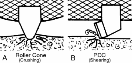
Roller cone bits crush formations as they drill, whereas fixed cutters drill by shearing formations (illustrated in fig. 1). Nozzles supply the mud that softens the drilled formation while shock subs absorb the shock that originates from the bit due to hitting formations. There is also a mud motor, which the report shall cover thoroughly in later sections. The third component is a non-magnetic collar, which stops steel parts from interfering with the magnetic field due to the sensitivity of sensors. The fourth component is the MWD, which is linked to the BHA. Stabilisers are also parts of the components, and they foil the axial and lateral vibrations. Stabilisers have fins, which are positioned in a manner that ensures that BHA remains in a central location. The system also has a heavy weight drill pipe (HWDB), which engineers can fix and assemble in the rig just like the drilling bit.
The HWDB stops the pendulum effect that happens in drilling processes in the vertical hole. BHA assembling involves the use of crossover subs. Crossover subs have different thread designs to match with the different types and sizes of pipes. Drilling collars are pipes that freely allow the mud to flow through them. Drilling collars also maintain the whole tension of the BHA and provide a weight on bit. The weight on bit refers to the aggregated load added to the drill string in order to provide momentum for the crush formations. The rate of penetration reflects the instant velocity of bit and drill string.
Powering Drilling Process
All drilling processes have two types of power found in the drilling string, which include the BHA arrangement and drilling collars. The power rotates the entire drilling string by the use of the attached rotary table on the rig flower. The rotary table consists of an electrical motor with a high-speed of rotation, which drives the drilling process. Mud flow also supplies power to the drilling process, but this power only drives the drilling bit and the mud motor.
Measurements While Drilling (MWD)
MDW is an electromechanical gadget, which is applicable in the guiding process and collecting data during the drilling procedures. The main role of the MWD is to collect and transfer the required data during the drilling process. MWD consists of traks, which have various sensors for different functions. Traks in the system have different features and designs, but they all share a common elementary sensor known as the survey sensor.
Survey Sensor “Directional Navigation”
The original MWD specifically served the role of collecting and transferring data. However, sophisticated sensors have emerged to include other roles. The main role of the survey sensor is to provide the location of the BHA, which involves inclination and Azimuth coordination. Inclination shows the degree or the extent to which the BHA has deviated from the vertical angle while Azimuth shows the BHA angle in relation to the magnetic north axis and tool’s axis. Survey provides effective way of guiding the drilling process of the wellbore. Survey enhances how drillers develop high side or drop low side angles. Survey devices consist of an accelerator and a magnetometer, such as “Gx, Gy, Gz, Bx, By, and B”. The accelerator has an inclination reading in m/s2 while the magnetometer Azimuth reading is in the form of micro tesla. However, the Azimuth requires a correctional algorithm in order to eliminate errors that originate from the true north magnetic pole, which interferes with the survey readings.
Gamma Sensor
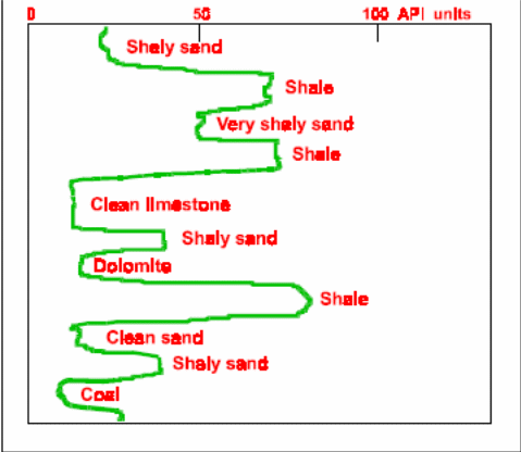
All processes of the earth’s formations bear elements of radioactivity radiations in different quantities. The sensor can determine the type of the formation, such as dolomite, sand, and coal. Generally, oil deposits are in the sedimentary rocks. However, the litho logy of the formation is likely because of the availability of various isotopes in minerals like potassium and uranium linked with them (as shown in figure 2 by the American Petroleum Institute). The system depends on a crystal emitting light, which flashes and interact with the gamma rays. A high voltage multiplier captures the flashes for amplification to the electrical current.
Resistivity sensor
A resistivity sensor is an electrical resistance of the current flow ‘impedance’. Generally, most of the earth’s formations have perfect insulators. However, the earth’s formations with salt water in ionic bonding that contains clay minerals lack qualities of perfect insulators. The resistivity sensor searches for the true sensitivity, Rt. This process involves electrical emission via an electrode (collar), which returns later after an emission. It applies Ohm law.
R= KV/I “ohm”
- k is the geometrical factor of the emitting electrode.
- V voltage measured between electrode and formation, and the current, which result in the same resistivity.
Resistivity sensor helps in identifying shallow gas and percentages of hydrocarbons.
Vibration Sensor
The drilling process entails many vibration activities. This leads to the need for another sensor. MWD reading is prone to interference from the vibration, and there is a need to avoid vibration as much as possible. This is a valid stick slip sensor. Normally, there are three common types of vibration. First, there is the axial vibration x and y. This type of vibration results from the increase in WOB beyond the recommended level, and it can cause BHA failure. The second type of vibration is the lateral vibration, which is potentially risky than the axial vibration. This type of vibration requires a stabiliser in order to avoid failure. Finally, the stick slip (SS) is the most dangerous type of vibration. It is common in the drilling process. Stick slip happens when the tool rotates and stops for a given period while the bit rotates in the opposition direction. SS causes mechanical stress (torsion) on the drilling pipes and make them to stick in the formation, i.e., the BHA cannot move either up or down in the drilling process. It can also cause the formation to collapse. Stick slip could also result from stick formation, which takes place when it exceeds the bit lifetime, in low torque and high mud weight. In case SS happens, engineers can adopt two methods to handle it. First, they can apply the safest method of picking up the BHA and stopping the drilling process. The second option involves enhancing the WOB in order to pass the formation with high ROP.
Other services In MWD and Traks TM names
Trak is a name that accompanies different services offered in drilling processes. In order to avoid complexity, it is imperative to abbreviate them. The coop work involved working with the Navi-gamma trak, on trak, Litho trak, and Azi trak. Hence, this report provides in depth accounts of these traks. The following table provides other traks and their features. These traks can also be combined in the BHA sensors in order to enhance their efficiency and effective results.
Table 1: Halliburton trak services.
Navi-GammaTrak
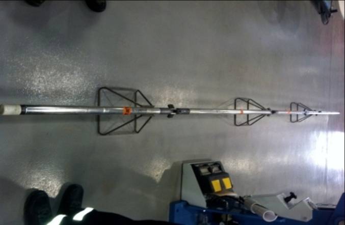
Navi-Gamma trak has unique design relative to other ordinary traks. This is the basic service, which Halliburton offers. This type of trak relies on the battery power system, and it is mainly useful in slim and narrow holes. It works alongside the UPA mud pulsar. Navi-gamma trak can be placed inside the collar due to its design, unlike other designs with have hatch covers. This type of trak only provides navigation and gamma ray logs. It has tandems, which absorb vibrations. The figure below shows a Navi trak before installation in the collar.
On trak
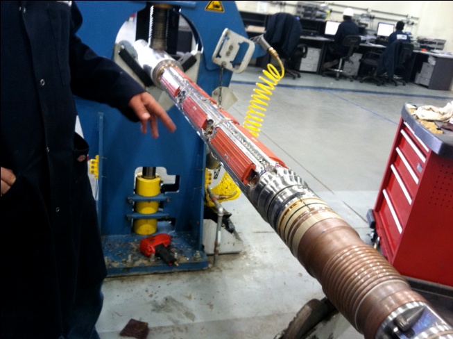
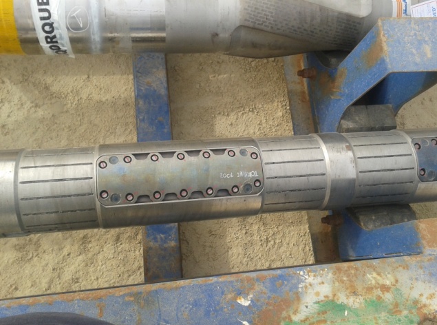
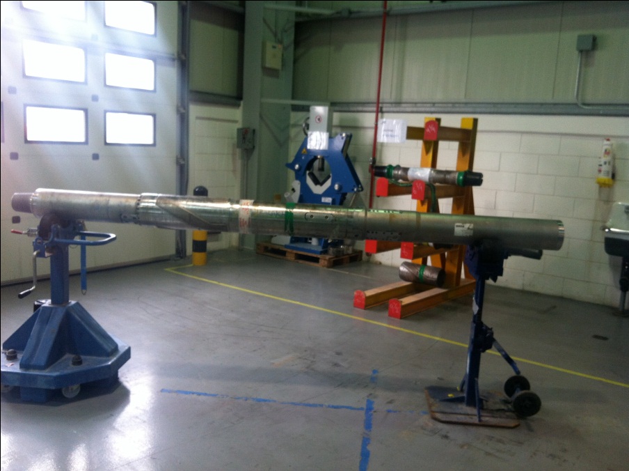
On trak is the most popular trak in the whole Halliburton fleet. It provides several services, include gamma ray, Azimuthal gamma ray, annular pressure, directional surveys, vibration, and stick slip, as well as formations resistivity. On trak is complex and advanced than the navi-gamma trak because of its design and sensor housing units. It also has advanced power supply, which relies on the BCPM turbine to supply electricity to the sensors rather than the battery system. Figure 4 and 5 below show on trak sensors before and after assembling.
LithoTrakTM
The litho trak nuclear service has Optimised Rotational Density and Caliper Corrected Neutron measurements in order to provide formation bulk density, photoelectric effect, neutron porosity, and borehole acoustic caliper. Moreover, the trak acquires the density, photoelectric factor, and acoustic caliper measurements azimuthally in order to enhance a sectored imaging of measurements. The litho trak offers two critical properties, which include permeability and porosity. These properties are useful in ascertaining the content of the reservoir. The system uses a radioactive source “cesium 237”. The coop session does not cover litho trak because it requires specialised expertise and knowledge for handling radioactive sources. The human body has the ability to store radioactive radiations. This system works by transferring neutrons to formation to hit the ‘isotopes’. The isotopes come back with a given number of wavelengths. Every number of a wavelength shows formation type. The LWD trak is appropriate for this function because of its near and far detectors.
Directional Drilling Concepts and Principles
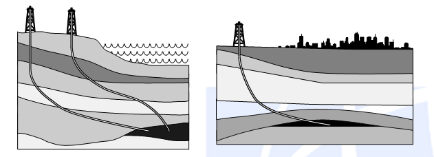
Directional drilling (DD) concepts resulted from the need to derive optimal benefits from oil and gas reservoirs. Figure 6 below illustrates two examples in which the DD is applicable. Some of the DD necessities include multi drilling purposes in inaccessible areas, on shore, avoiding salt domes, off shore and relief well (3, 21).
Directional drilling relies on mud motors because they affect deflection in the drilling process. Usually, every 100 ft has a determined deflection angle in order to avoid stuck and force misplacement. Mud motors have positive displacement and rotary closed loop steerable motors. These two types of mud motor work in different ways.
Positive Displacement Mud Motor
Adjusted Kick off Motors
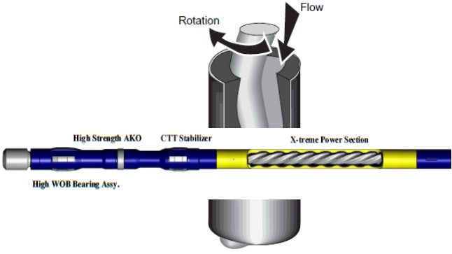
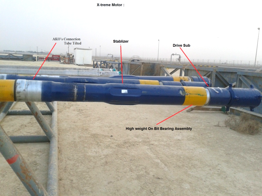
In the introduction part, the report highlighted how the directional drilling is important in drilling processes. Directional drilling relies on mechanical principles of the positive displacement motor. The mud circulation powers the system through the down hole as illustrated in figure 7. This action results in the rotation and torque to drill string, “BHA and drill collars” without any requirement of rotation from the rotary table left in the rig floor. The PDM has four essential parts, which are optional float valve, power section, flexible shaft, and bearing assembly as shown figure 8 and 9 under the whole PDM components.
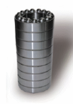
The first part is the optional float valve, which acts as a check valve that stops a backflow into the motor cavity and sealing. The power section of the motor is built from both the rotor and stator, and it is where the hydraulic energy from the drilling fluids changes into mechanical energy. In turn, it provides the torque, bit speed, and the residual heat, i.e., lowering the down hole temperature. A flexible shaft links Halliburton’s mud motors in the lower section of the rotor and the upper parts of the drive sub. The shaft transmits power from the power module via the drive sub to the bit. Still, there are universal flexible shafts or joint assemblies, which change the motion of the rotor into concentric rotation for the bearing assembly. The bearing assembly has several balls and races designed to bear the high down hole weight need to penetrate the formation as illustrated in figure 10.
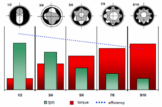
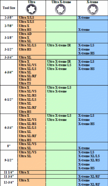
Bearing assemblies are in the upper and lower radial bearings where they can support the side force on the drive sub. There are mud-lubricated parts, which provide support to the drive sub. Mud motor relies on torque and rotation for efficiency. The motor torque improves as the differential pressure develops. Rotor and stator are in the helical lobes, which develop seal cavities to allow the mud to shift in unusual motion. Specifically, rotor has low lobes relative to stator for motion purposes. Rotor and stator are built to support the weight on the bit. The table 2 indicates that an increase in the number of lubes results in an increase on torque while the RPM decreases. The type of work influences the decision-making processes on motors. There are Ultra and X-treme motors. X-treme motors come in different sizes as indicated in table 3. Every motor design accounts for optimal features in terms of maximum speed, efficient drilling, or high torque.
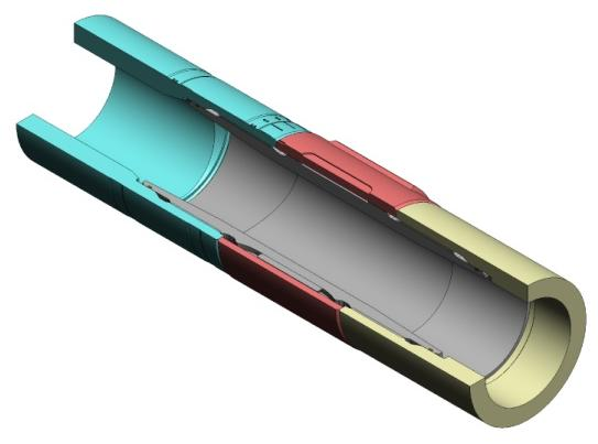
The mud motor has two different types of motion, which are sliding and rotation. Rotation involves a conventional movement in which the BHA rotates from the rotary table in the rig floor. On the other hand, sliding is the movement in which only the mud motor and the bit rotate. There is an angle due to the adjusted kick off system or connection tilted tube. The AKAO design consists of two cylindrical thread joints (see figure 11). The upper thread joint of the double pin and the box joint of the connection tube tilted (CTT) bear a tilted thread joint that result in a bend in the housing when attuned. There are marks on the bottom of the CTT for efficient adjustment of the AKO settings. The alignment mark is on the groove on the upper section of the sleeve. Sliding is necessary for developing inclination because it is the only effective way of building an angle. The additional of BHA does not require the system rotation, but sliding issues arise from the slow motion and doglegs. Doglegs are high and acute angles from AKO. The report would cover calculation associated with doglegs severity in casing and cementing.

2-Closed Loop Automated Drilling Systems
Rotary Steerable systems
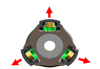
The rotary steerable system was developed due to challenges associated with the mud motor. This was the first motor to apply the automated principles in drilling. Auto trak consists of three hydraulic ribs as illustrated in figure 12. The ribs push formation walls when they are open. This movement allows the BHA to rotate in the opposite direction. Hydraulics has various designs of angles in order to obtain the optimum or minimum inclination as required. Auto trak Steering Unit (see figure 10) consists of a non-rotating sleeve that supports the expandable ribs. This is a non-rotating sleeve, but it is not permanently static because it rotates at a slow pace of less than 10-20 rotations in every hour. This enhances weight transfer to the bit and eliminates any possible failure in the drilling process or damages to the borehole. The steering sleeve has three separate micro-hydraulic units, which operate independently. They include a near-bit-inclination, sensor package, and the control electronics. Transmission of electrical power and communication from the non-rotating sleeve to the rotating sections of the unit without physical contact and connected requirement for mud seal occur due to an inductive coupling.

The electrons follow and allow the system to operate as designated units. It then allows the ATK to run continuously with a fixed inclination in order to correct the path and fix vibrations, VSS. ATK operates through mud flow pulses, which has a device known as an adjustable bypass actuator (see figure 14). The unit works by diverting the mud flow in milliseconds and creates pulses in a binary way that ATK electronics understands. Orders are sent through ABPA without any need to move to the rig floor, which enhances full flexibility, target inclinations, and well profiles.
The inclination could range from 0° to 90°. The two major innovations of Rotary Steerable Systems are:
- Continuous Drill string Rotation while Steering
- Highly automated steering control and easy directional target changes via surface command
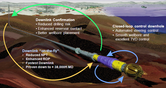
These two parts provide magnificent improvement in drilling operations. The directional drilling with a Rotary Steerable System requires communication between the surface rig and the down hole BHA component. The process needs a mud pulse telemetry and wired drill pipe for a direct electronic link for establishment. The command can originate from the surface and then sent to the down hole (downlinks) with AutoTrak systems. Downlinks can reach the bottom hole without interrupting the drilling process, which saves time. Figure 15 illustrates the data transfer from the down hole. The down hole loop control manages the steer force every second automatically in order to remain aligned to the needed direction with the desired force.
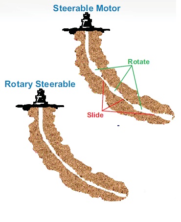
Compare and Contrasts between Conventional and automated
AutoTrak Rotary Steerable systems are responsible for constant tuning of the steering direction with no sliding or orienting. The system is better than mud motor, but generally weaker than the same in developing angles. Doglegs or acute angles are simple to get from Autotrak. A high performance drilling that exceeds 200 ft/hr, Halliburton combines AutoTrak, and conventional systems (figure 16 highlights various output drilling processes).
Data Mining Tasks
Mud is the driving fluid for the drilling process. An innovative application of mud involves the transmission of information. This happens through a device known as a mud pulsar, which has made the process to be simple. The mud pulsar allows the mud to flow or not to flow within milliseconds. This results in carrier waves with almost the same speed as sound (figure 17, 1-19). The mechanical device in the mud pulsar controls both closing and opening of the system. After that, the surface sensors detect pulses and transfer them where necessary. Halliburton works with positive mud pulse telemetry (MPT), which relies on a hydraulic poppet valve for short restriction of the flow of the mud via an opening in the tool to create pressure as a positive pulse or pressure wave. The positive pulse travels backs to the surface and noted at the standpipe (1, 19).
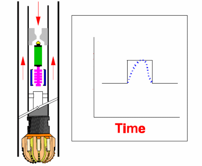
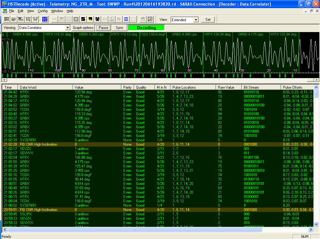
After the transmission of the mud pulsar to the surface, they adjust to the surface as waves via sensors and change to electrical currents in mill amperes. A translating system (SARA2) interprets the waves as readings and shows them on the screen. SARA2 consists of six parts, which work together to control the entire process. The critical component is the PNC or the pump noise canceller. PNC eliminates any possible disruption from the pump stroke or any other gadget. A chrimp detector is also an important component, which notes any waves and interprets their values in terms of figures.
Mud Pulsars
Mud pulsar is also important for transferring electrical power to sensors within the MWD. The main components of the mud pulsar are turbine, alternator, and generator. The company has three types of pulsars, which are UPA, BCPM1, and BCPM2. These pulsars have different features, and data transmission properties differ in all pulsars. For instance, UPA has 0.8 sec while BCPM1 has 0.4 and BCPM2 0.03 S. UPA differs from BCPM because it does not transfer electric current to the sensors, which depend on batteries for power. Its design is inferior due to scattering of heat, which causes electronics to burn. On the other hand, BCPM has both the alternator and rotor-stator-generator. Hence, it generates and turns voltage into DC voltages, 33V. The conduction of electric power occurs through the gold-copper rings found in the links between MWD and the pulsar.
Figure 19: UPA mud Pulsar

- Mud Inlet.
- Restrictor.
- Main Valve (bell).
- Poppetvalve.
Figure 8 shows UPA pulsar and describes the creation of a mud pulse. The mud flows through the area of the pulsar into the mud inlet. A solenoid controls a poppet valve to create a pulse, which closes the narrow mud channel above the valve. This process creates up the pressure in the main valve section, which results in the movement of the main valve bell upwards and reduces the mud flow area close to the restrictor. This makes the flow area to be small and increases the pressure in the region of the restrictor, which rises to the surface through the mud channel. The speed of the pulse depends on the mud properties, but it is usually 1000m/s–1450m/s. The poppet valve must return to its idle status in order to complete the formation of the pulse. This releases the pressure in the main valve bell section. The main valve then assumes its open position as the pressure in the restrictor region returns to idle status. BCPM and UPA differ on the principles, which guide the working mechanism of the poppet valve (right-lift).
How signal Travels form down hole to the displaying Screen
The mud pulses identified by the surface sensors appear on the screen as decoding. The mud pulse passes through SARA2, which eliminates vibrations, noise from the pump, and interference. Decoding reflects vibrations in the down hole in lateral, axial, and stick slip via VSS sensor. It also captures gamma ray readings and temperatures at the bottom. Decoding also reflects a tool face or a bit face as either high or low inclination. This shows the progress of the drilling process.
Tool’s failures
The case study covers tool failures and reasons for failures at Halliburton. Failures occur due to different reasons and have different outcomes. The study of failures in tools enhances understanding of their features and properties. Knowledge gathered allows the company to upgrade its tools. It also helps in determining causes of tools failures. Failures in tools relate to three critical areas, which include ARAMCO, Halliburton, and rig company. Failures could result in fines and monetary costs to a company that is responsible for them. Many failure cases are common in the mud processes.
Mud Motors Failures
From the previous section, the cooperative report has shown that a mud motor consists of three parts, which are power section, bearing assembly, and stabilisers and drive shaft.
Power section
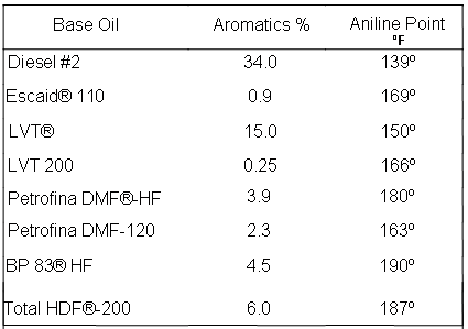
The stator consists of an elastomer with some specific features. Elastomer faces problems of arising with aromatics in diesel when diesel or oil based mud of 60% to 80% is used. The aromatics interfere with the aniline point of the diesel, which makes the elastomer to expand and wear due to mechanical erosion (see figure 27). Oil based mud has other elements, which diesel may not have, especially aniline point (table 5). Aniline point reaches when the high polar aromatics in the liquid meet as miscible with the same volume of oil. A low point of aniline leads to a greater elastomer.
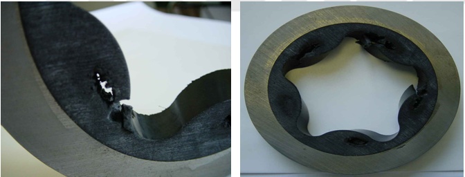
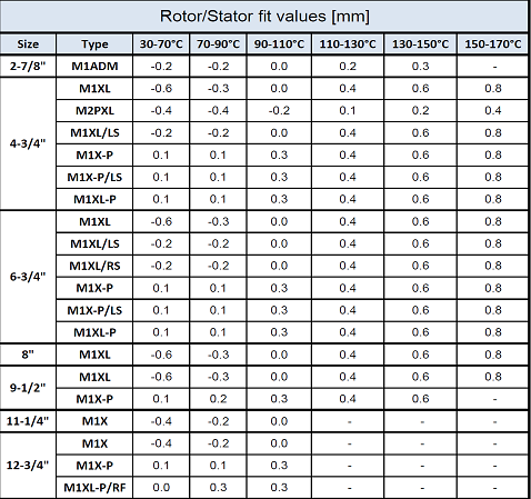
The solution leads to changes in the rotor-stator based on the prevailing level of the temperature (see table 6). The changing fits lead to increased expansion of the stator during operations. The solution works by reducing failure time by 50% and achieves a drilling of 100 hours. Another expensive solution exists, but Halliburton benefits from high oil mud quality. ARAMCO compensate for failures of up to five times the original cost of the mud motor.
Bearing assembly
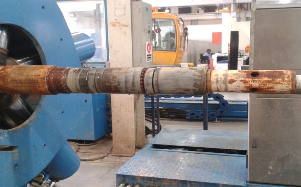
Every motor has a specific function as indicated in the performance sheet, which it must adhere to strictly. Any attempts to exceed the weight on bit results in a shorter life of the bearing, which leads to the system failure as illustrated in figure 30.
MWD failures
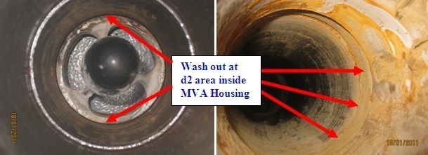
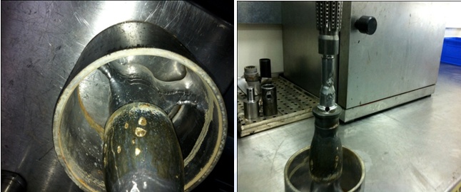
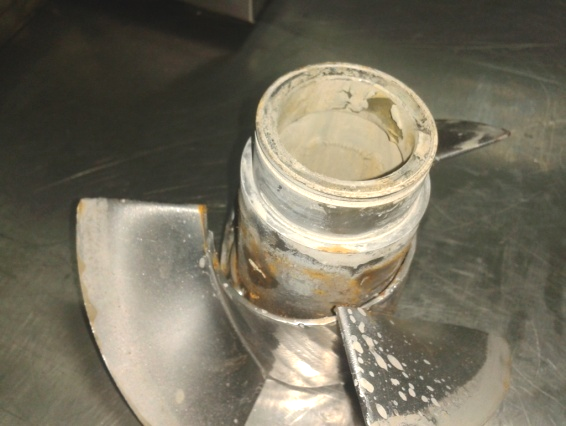
MWD contains mud pulsars and sensors. Sensors have electronics, which are prone to short circuit, burns, and other challenges. This failure results from excessive heat dissipation. LWD sensors are most risky because of their nuclear elements. Although the nuclear elements are in small quantities, they remain extremely dangerous due to radioactive radiation, which could poison ground water. The mud pulsar may fail to supply power to sensors or stop pulsing. Mud pulsars may fail because of washout, corrosion, and other technical and mechanical reasons (figure 31, 32, and 33 show some cases of mud pulsar failures).
Other general reasons for failures
Mud could be responsible for several failures for the entire drilling string. One major failure is the lost in hole failure. This failure implies that the whole drilling string cannot be retread. Drilling string is expensive, and many oil and gas firms would like to avoid the lost in hole failure. Mud weight is a critical element that reduces any chances of formation fluids running into the well hole, i.e., overflow. The process depends on hydrostatic pressure, which results from the mud in order to match the force of gravity from the walls of the well. Formation collapse is the most dangerous outcome that could happen in drilling processes. It results from low mud weight and pressure. The mud is also expensive and any failure could disrupt its cycle. Hence, it must be prevented from any loss to the formation. Engineers should observe washouts by ensuring that the BHA does not access soft formations. Washout is a failure that enlarges the size of the hole. An enlarged hole could be difficult to cement, increase velocity, damage BHA, and create chemical attacks on the drill string.
Conclusion
The cooperative work provides the best opportunity to apply knowledge gained in the university to a real industrial setting. I work for at least 12 or more hours at the rig site during my cooperative work. I assumed the role of an engineer who could run the entire drilling process. My courses equipped me with knowledge to apply in such environments during operations (see figure 34). The coop provides a wealth of knowledge that goes beyond physical work and helps one to determine a future career. I have gained experiences on how sensors within the trak work based on the measurement while drilling technology. I have also noted how mud powers the entire process and any properties that could influence the drilling process. Moreover, I have also understood how mud motors operate in real drilling situations. There were also calculations that I had understood from the implementation of the drilling process. Finally, I learned about several reasons that could cause failures in tools and practical ways on how to avoid them. In fact, Halliburton coordinators have recommended me for employment at the company after my graduation. This will determine my career in Sha’a Allah. Overall, the cooperative exercise covers all fundamental aspects of theories and practical knowledge that all engineers require.
References
Halliburton. Halliburton: The Middle East region. 2013. Web.
(1997). Baker Hughes Inteq guide to measurement while drilling. Houston Texas, USA: Baker Hughes Inteq.
(2011). Decoding Hand Book. Baker Hughes.
(1997). Directional Drilling Training Manual. Schlumberger
(2009). Navi drill Motor handbook. (11th ed.). Baker Hughes Inteq.
(1996). Oil Field Familiarization. Houston Texas, USA: Baker Hughes Inteq.
(1997). Wellbore Positioning Training Manual. Houston Texas, USA: Baker Hughes Inteq.