Introduction
Initially, Galileo started to explore the stresses induced in beams by bending loads but the theory we accepted today is mainly proposed by the mathematician Leonard Euler (1707-1783). A beam undergoes or develops normal stresses lengthwise with a varying magnitude. The tension is maximum at one surface whereas zero at the mid-plane of the beam with maximum compression at the opposite surface. Shear stresses are also induced along with the normal stresses. In the case of the large length-to-height ratio of a beam, these shear stresses can be neglected.
Normal stress
When a beam is subjected to a positive bending moment, it will gain a tendency to possess a concave-upward curvature. It implies that the material near the top surface of the beam is in compression with the x-direction with the bottom surface in tension. There exists a neutral axis of the beam. It is a transition between the compressive and tensile regions where the stress becomes zero in magnitude. In case of strong tension but weak compression forces present in a material, resulting in the failure at the upper compressive surface.
An expression is desired that relates the magnitudes of axial normal stresses to the shear and bending moment within the beam in correspondence with the shear stresses induced in a circular shaft by torsion.
- Geometrical statement: as shown in the figure given below, the transverse planes within the beam remain planar under bending but are rotated by an angle θ on the neutral axis.
The expression for the curvature is,
dθ/ds = (d2v / dx2) / [1 + (dv / dx)2] 3/2
also, θ ≈ dv / dx, the squared derivative in the denominator is quite compared to 1.
The angle can be expressed by the given relation:
u = – y dv / dx
Where, v(x) = the x-derivative of the beam’s vertical deflection function v(x).
y is measured positive upward from the neutral axis.
- Kinematic equation: the x-direction normal strain εx is expressed as the gradient of the displacement:
εx = du/ dx = -y d2v / dx2
Where d2v / dx2 = the spatial rate of change of the slope of the beam deflection curve, known as the curvature of the beam.
The strains are zero at the neutral axis where y = 0.
Compressive (negative) above the axis, tensile (positive) below the axis.
These quantities are directly proportional to y, that is they increase linearly with y as the shear strains increase linearly with r in a torsionally loaded circular shaft.
Constitutive equation: using the Hooke’s law, the stresses can be expressed as
σ = E εx = -e E d2v / dx2
This derivation is not applicable to linear elastic materials. Therefore, the axial normal stress such as strain linearly increases from zero at the neutral axis to a maximum value at the outer surfaces of the beam.
- Equilibrium relations: the total axial force generated by the normal σ x stresses must be zero when no axial (i.e. x-direction) loads are applied externally to the beam.
∑ fx = 0 = ∫A σX dA = ∫A –y E d2v / dx2 dA
∫A y dA = 0
Also, y = (∫A y dA) / (∫A dA)
Where, y = distance from the neutral axis to the centroid of the cross-sectional area. The stresses increase at the same linear rate both above the axis in compression and below the axis in tension. The resultant horizontal force can be zero only if the axis is at the centroidal position. Hence the beam is in the horizontal equilibrium state. Still a net clockwise moment is produced.
∑ MO = 0 = M + ∫A σX. Da
M = ∫A (yE d2v/dx2). ydA = E d2v/dx2 ∫A y2 dA
Thus, the moment must equal the value of M(x) at the value of x around point O.
∫ y2 dA is the rectangular moment of inertia with respect to the centroidal axis, which is denoted by I.
I = ∫h/2-h/2 y2 b dy = bh3 / 12
The beam curvature is
d2v / dx2 = M / EI
Therefore the stress can be expressed as;
σx = – y E M / EI = – M y/ I
Shear Stresses
Transverse loads cause shear effects that tend to slide vertical planes tangentially to one another similar to the playing cards sliding after one another. The stresses related with the shearing effect are added to the vertical shear force V. It is important to study the distribution of these stresses all over the cross-section of the beam. The horizontal shearing stresses will be zero at the upper and lower surfaces of the beam unless some traction is present in order to balance these forces. The shear stress on the vertical plane is accompanied by an opposite stress on the horizontal plane because τ xy = τ yx.
Hence it is clear that these stresses will attain a maximum value somewhere between the beam.
In order to study the variation in the horizontal shear stress with vertical position y, let us assume a free body of width dx cut from the beam at a distance y above the neutral axis. The moment gained at the vertical left face will be M(x) whereas on the vertical right face it will be M + dM. an increase in the moment dM along the distance dx will imbalance the horizontal force caused by the normal stresses because the horizontal normal stresses are directly proportional to the moment (using σx = M y / I ).
Τ xy b dx = ∫A’ (dM ξ / I) (dA’ )
Where, b = width of the beam at y.
ξ = dumm y height variable ranging from y to the outer surface of the beam.
A’ = area of cross-section between the plane at y and the outer surface.
Lets use dM = V dx,
Τ xy = V / IB ∫A’ ξ dA’ = VQ / Ib
Where Q (y) = ∫A’ ξ dA’ = ξ A’, it is the first moment of the area about the neutral axis above y.
Principal Stresses
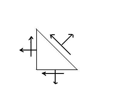
Assume a body under the action of both the normal axial stresses as well as shear stresses. The shear stresses Tauxy and Tauyx must be equal in order to attain the condition of static equilibrium. Consider an object, where a plane cut through it at an angle θ. Both the axial stress σθ and shear stress τθ will act on this plane. We can obtain the forces on each surface if the mathematical product of these stresses and the appropriate areas are calculated. The equilibrium equations can be written by applying the static equilibrium conditions.
The sign convention usually considered is given below:
- Tensile stress is considered as positive whereas compressive stresses are taken as negative.
- The shear stress is considered positive when a anti-clockwise torque (couple) is produced by a pair of shear stress acting on opposite sides of the element.
- The positive direction for the angle is when an angle is measured from the vertical anti-clockwise to the plane.
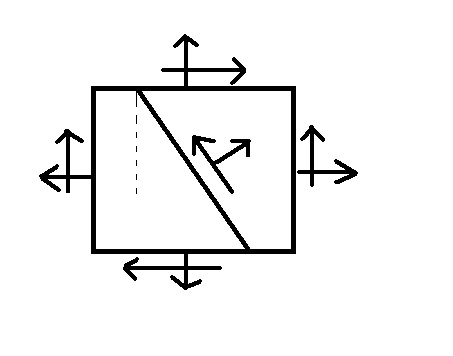
Now equilibrium equations can be expressed as:
Sum of horizontal forces = – σ X (A cos θ) – τ XY (A sin θ) – τ θ A (sin θ) + σ θ A (cos θ) = 0
Sum of vertical forces = – σ Y (A sin θ) – τ XY (A cos θ) – τ θ A (cos θ) + σ θ A (sin θ) = 0
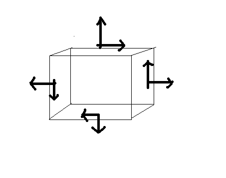
These equations can be solved simultaneously. The final result obtained will be:
σ θ = (σ X + σ Y) / 2 + [(σ X – σ Y) / 2] (cos 2θ) + τ XY (sin 2θ)
τ θ = – [(σ X – σ Y) / 2] (sin 2θ) + τ XY (cos 2θ)
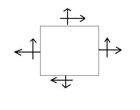
These equations are known as transformation equations. Principal stresses are the maximum and minimum stress values and principal planes are the planes at which they occur. The shear stress will be zero at the principal planes where the axial stress is either maximum or minimum. The different values of principal stress can be expressed as:
σ max = (σ X + σ Y ) / 2 + √{[( σ X – σ Y) / 2]2 + τ XY2}
σ min = (σ X + σ Y ) / 2 – √{[( σ X – σ Y) / 2]2 + τ XY2}
τ max = ± √{[(σ X – σ Y} / 2]2 + τ XY2}
Tan 2θ = τ XY / [(σ X – σ Y) / 2]
The planes for maximum shear stress differ by 45° from the principal plane.
There are few more relations for the principal stresses in terms of other parameters:
σ max = (σ X + σ Y) / 2 + τ max
σ min = (σ X + σ Y) / 2 – τ max
τ max = (σ max – σ min) / 2
Pressure Vessels
Pressure vessels are used to carry fluids, vapors or gases at pressure levels greater than that of the atmospheric pressure. These vessels contain a large variety of substances used for various industrial applications in the fields of chemical, food and beverage, plastic industries, oil and fuel and pharmaceutical. The potential for rupture and leakage always exists whenever a substance is stored under pressure. Improper maintenance and design of vessel increases the risk of pressure vessel failure. This can cause severe hazard if a vessel contents are toxic or gaseous substances. Manufacturer should take precautions when creating a pressure vessel in order to limit the chances of vessel failure.
There are various types of pressure vessels like1:
- ASME tanks are pressure vessels that meet the standards set by the American Society of Mechanical Engineers.
- Autoclaves are closed pressure vessels that use steam and high pressure to sterilize instruments.
- Cookers are a type of pressure vessel that is used to bring about a physical change in their contents. Examples of this are digesters, vulcanizers and rendering tanks.
- Fired pressure vessels utilize fuel combustion to generate heat. Examples include boilers, furnaces, gas water heaters and autoclaves.
- Heat exchangers include a variety of configurations of vessel equipment in which heating or cooling is performed on one side of the vessel and the opposite conversion on the other side2.
- Kettles are pressure vessels that use steam to heat fluids.
- Pressure tanks are vessels that hold contents at pressure levels greater than atmospheric pressure.
- Rotating pressure vessels usually contain steam, which is then used to dry articles such as paper, fabric or plastics. The materials are passed over the rotating vessel via rollers to come into direct contact with the emitting steam.
- Steam jacketed vessels are used to heat liquid to a moderate degree. Steam is distributed between the inner and outer shells of the vessel and is used in the commercial preparation of foods such as candy.
- Storage vessels include air tanks, hot water tanks, propane or other gas tanks, which contain contents under pressure when needed.
- Transportable vessels are in contrast to those that are stationary. Examples of such are those are road or rail tankers; propane and gas tanks are considered to be in this category.
- Unfired pressure vessels are not exposed to direct heat. Generated heat, if any, is produced through electric heat or steam, and sometimes through the chemical reactions of vessel contents.
- Water pressure tanks hold water at levels exceeding atmospheric pressure.
The most commonly used pressure vessels are:
- Thick walled pressure vessels are the least common. They are any cylinder [shell] ratio that is 10% or more the ratio of the thickness to the inside diameter.
- Thin walled pressure vessels are one of the most common of the vessels. They are any cylinder [shell] ratio which is 10% or less of the ratio of the thickness to the diameter, or a pressure vessel is thinned walled if the diameter is 10-times or more of the thickness.
The logistics of pressure vessel creation is determined during the design process. Engineers must determine the temperature, pressure level, size, material components and shape while designing process. Before deciding these factors, the corrosion and abrasion potential of the vessel should be considered. Before deciding the material and shape, pressure levels should be taken into account. Vessels range from a few hundred pounds per square inch (psi) to measuring up to 150,000 psi. Temperature must be considered before the selection of the material. Mostly, pressure vessels are cylindrical in shape but the contents under high pressure are often stored in the stronger spherical vessels.
Due to all these factors and the reason that the pressure vessels can with stand a temperature range exceeding 750°, safety becomes an inevitable feature. There are standard regulations and formulas to guide the manufacturers to avoid potential hazards associated with pressure containment. A Boiler and Pressure Vessel Code are provided by the American Society of Mechanical Engineers (ASME) on which engineers base pressure vessel design. Engineers follow few other codes like American Petroleum Institute (API) but the ASME code still remains the most common standard.
Whirling of Shafts
A shaft can go into transverse oscillations as soon as it starts its rotations. The centrifugal force due to the imbalance of shaft can induce the shaft to vibrate. When this shaft rotates at a speed equal to the natural frequency of transverse oscillations, these vibrations becomes large enough to show the whirling of the shaft. This phenomenon can cause damages to the heavy rotary machines like turbine generator sets. The system must be properly balanced in order to reduce this effect and it should be designed to posses a natural frequency different to the speed of rotation. The critical speeds must be avoided while starting or stopping such machines to prevent the damage of the turbine blades and bearings.
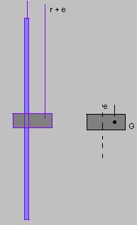
Let us assume a weightless shaft with some mass M at the middle. It should be taken into account that the centre of mass does not lie on the centre line. The centrifugal force will cause it to bend out as soon as the shaft rotates.
Let this deflection be. Therefore the centre of gravity will be r + e.
Let the angular velocity of the shaft be ω rad / seconds. The transfer stiffness is k t N / m.
Hence the deflection force, F = k t r
Centrifugal force = M ω2 (r + e)
Using k t r = M ω2 (r + e)
r = [M ω2 (r + e)] / k t = [M ω2 r / k t] + [M ω2 e / k t]
r = (M ω2 e) / [k t (1 – M ω2 / k t)]
Also, k t / M = ω 2n
r = (ω2 e) / [ω 2n (1 – ω2 / ω 2n)] = e / [(ω n / ω) – 1]
Therefore, when ω n = ω, r = e / 0 i.e. infinity.
This implies that the shaft will whirl at the natural frequency no matter how small is the imbalance distance e. perfect balancing is not practically possible therefore the whirling should be avoided at the machine level.
Cases
Simply supported
In this category, the ends are free to rotate normal to its axis.
f = (π / 2) (n 2) √(g E I) (wl4)
Where mode n = 1,2,3…..
Fixed ends
In this category, the lowest critical speed f = 3.562 √ (g E I) (w L 4 )
The higher critical speeds are expressed as, f = (π / 2) (n + 0.5)2 √ (g E I ) (w L 4)
Where n = 2, 3, 4….
Since the lowest speed almost corresponds to n ≈ 1.
Cantilever
In this category, the lowest critical speed, f = 0.565 √ (g E I ) (w L 4)
f = (π / 2) (n – 0.5)2 √ (g E I) (w L 4)
where, n = 2,3,4…..
Since the lowest speed almost corresponds to n ≈ 1.
Plastic Deformation of Materials
Plasticity is the property of material to undergo a non-reversible change of shape in response to an applied force. The transition from elastic behavior to plastic behavior is called yield. In various materials like ductile metals, tensile loading applied to a sample will be responsible for its elastic manner. With an increment in load, an increment in the extension can be observed. The piece will return to its original size when the load is removed. But when this load exceeds a threshold value (i.e. the yield strength), the extension will increase more rapidly in this region as compared to the elastic region. But some amount of extension remains when the load is removed.
Plasticity is the property of a material to undergo large deformation without fracture. This property is exhibited by most of the metals. Perfect plasticity is the property of a material to undergo large shear deformation without any increase of stress. Visco-plastic materials are those plastic materials that are not perfectly plastic.
Deformation
The plasticity is explained with the help of various mathematical descriptions. According to the deformation theory using Hooke’s law, stress tensor of order d in d-dimensions is a function of the strain tensor. This theory is not applicable for irreversibility. But this description is accurate in case of a small matter subjected to an increasing load.
Ductile materials can withstand large plastic deformations without fracture. Ductile metals become brittle, due to the work-hardening of the material when the strain becomes large enough and even ductile metals will fracture. Heat treatment like annealing can restore the ductility of a material in order to continue the shaping.
Fatigue Failures of Materials
Fatigue in materials is caused by the continuous cycling of the load. It is a damage caused due to the fluctuating magnitude of stresses and strains on the material. The fatigue cracks generate and propagate in the regions of severe strains. This entire process of fatigue is mainly divided into three stages:
- Crack initiation.
- Growth of cracks.
- Sudden fracture of the remaining cross-section.
Fatigue failures of materials are caused due to repeated loads below the static yield strength. It can cause failures in use. Most of the materials used today contain discontinuities, therefore most fatigue cracks initiate from discontinuities in the highly stressed regions of the component. The reasons for this failure may be design, discontinuity or improper maintenance.
Stress Ratio
The stress ratio is defined as the ratio of minimum stress to the maximum stress.
R = S min / S max
The value of R can vary according to the conditions and stress:
- R = – 1, when the stresses are fully reversed.
- R = – < 1, when the stresses are partially reversed.
- R = 0, when the stress is cycled between a maximum stress and no load.
- R = < 1, when the stress is cycled between two tensile stresses.
The fatigue life depends on the variations in the stress ratios. A mean stress component always has a substantial effect on the fatigue failure of the materials. A component will fail at lower alternating stress as compared to the fully reversed stress conditions when this tensile mean stress is added to the stresses with alternating values.
Preventions
Improvement in design: it is the most effective method to improve the fatigue performance. Stress raisers can be minimized by streamlining the parts. Sharp surface tears which are the outcome of punching, stamping, shearing or other processes should be avoided. The development of surface discontinuities during the processing should be prevented. The tensile residual stresses caused by the manufacturing process should be eliminated. Improvement in the details of fabrication and fastening procedures is always beneficial.
Creep
Creep can be defined as the tendency of any material to deform or to move permanently in order to relieve stresses. The deformation of materials occurs due to the long term exposure to levels of stress that are below the ultimate strength or yield of that material. It is more likely to be exhibited by those materials which are subjected to high temperature for quite a long duration, near their melting point. The creep is directly proportional to the temperature. The rate of damage occurred is a function of the material properties, contact temperature, stress applied and exposure time. Sometimes a component can be disabling forever to perform its functions due to the duration and magnitude of the applied stress which may cause large deformation. But moderate creep in concrete is desired sometimes since it eliminates tensile stresses which can cause cracking. The material strains over a long duration and finally fails instead of failing suddenly with a fracture. It is not caused due to sudden loading but the failure of material is caused by the creep strain in long durations. Usually creep occurs at 30-40% of the metals whereas 40-50% in case of ceramics.
Creep is an inevitable factor in designing various machines and appliances. Nowadays, lead pipes are not used anymore due to the reason that they can creep even at the room temperature. Creep can be observed even at very low room temperature because it depends on the melting points of the materials.
Stages
The strain rate is lowered with an increase in the strain. This stage is known as primary creep. At secondary or steady-state creep, the strain rate reaches to the minima and attains almost constant stage. During tertiary creep the strain-rate increases with rate in an exponential manner. The creep strain rate belongs to the secondary stage.
The process of creep depends mainly on temperature and stress. The different methods used are:
- Bulk diffusion
- Climb
- Climb assisted glide: it is the most common mechanism of creep.
- Thermally activated glide
- Grain boundary diffusion
General Equation
dε / dt = (C σ m / d b) e –Q / kT
where, C = constant, depends on the material and the creep mechanism.
m, b = exponents, depends on creep mechanism.
Q = activation energy of the creep mechanism.
σ = applied stress.
d = grain size of the material.
k = Boltzmann’s constant.
T = temperature.
Fracture Mechanics
It is the method for predicting failure of a structure containing cracks. It uses methods of analytical solid mechanics in order to calculate the driving force on a crack and experimental solid mechanics to obtain the resistance of the material to characterize fracture.
Fracture mechanics is an inevitable parameter required to improve the mechanical performance of materials and components. To predict the macroscopic mechanical failures of bodies, it applies the physics of stress and strain along with the theories of elasticity and plasticity to the microscopic crystallographic defects. Nowadays, fractography is widely used with fracture mechanics in order to study the causes of failures and the theoretical failure predictions with practical failures.
Failures of engineering structure can cause immense losses as in the case of Tay Rail Bridge disaster (1879). Engineering structures often contain cracks during the manufacturing or servicing period. It is important to determine the fracture resistance of engineering materials due to the fact that cracks can minimize the strength of the structure because of the loss of load-bearing area of a material property beyond the conventional strength. The fracture mechanics is required for the evaluation of the strength of cracked structures.
References
About Pressure Vessels. Web.
Andrew, W. (1995). Fatigue and Tribological Properties of Plastics and Elastomers. New York: Norwich.
Betten, J. (2005). Creep mechanics. 2-nd ed. London: Springer.
Dieter, G. E. (1989). Mechanical Metallurgy. (3 ed.). New York: McGraw-Hill.
Dunn, D.J. (1999). Solid Mechanics Dynamics. Web.
Hill, R. (1998). The Mathematical Theory of Plasticity. Oxford: Oxford University Press
Impact Loading. Web.
Roylance, D. (2000). Stresses in Beams. Cambridge MA, MIT.
Schutz, W. (1996). A history of fatigue. Engineering Fracture Mechanics 54: 263-300.