Executive Summary
The report investigates the internal and external designs of a domestic building located at 45 Chelmsford, Chelmer Village, and Essex. The report will be divided into two sections. Section A provides external components of the building. Section B provides the internal part of the building that discusses the installation of the electrical part and other internal features of the building. The internal part of the building consists of the floor plan and electrical installation. All the electrical installations used for the building are in line with the regulations of the British standard.
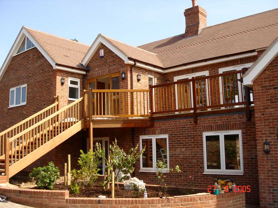
The building selected for this report was built in 2005 and is located at 45 Chelmsford, Chelmer Village, and Essex. The building serves as a domestic building for Mr. Paul Christine. Mr. Paul Christine provided the information in this report on 5th December 2009 (See the picture of the building in Figure 5).
External Features of the Building
This section provides the external features of the building selected. The external features consist of materials, bricks, blocks, and concrete used to build the house described in this report. In addition, the external features of the building also consist of a cavity wall, roof structure, and ground floor. (Ely, The Plan Collection, (2008). The building materials used for external features are a combination of the modern method of construction (MMC) and the traditional method. An MMC is a type of construction method that makes use of timber panels for construction. Typically, the MMC is the latest method of construction adopted because it is easy to construct. The home building chosen for this report has also adopted traditional methods of construction such as bricks, blocks, and concrete. (Parliamentary Science and Technology, 2003, Forticrete, (2008).
Walls of the Building
For the wall of the building, the aggregate concrete block is used for the wall. It should be noted that the fixing of the aggregate concrete block for the building embraces the medium fixing that filled the hollow portion of the building. The use of medium fixing of the building has heavy gauge fixing, and in the building, there are some design requirements that were followed. The block strengths are considered in the construction of the building. In addition, the building engineer choose the correct method of fixing the system that was suitable for weather hollow and suit loading. The wall design of the building is not impaired, and there are no holes whatsoever in the building. (Bassetlaw).
Meanwhile, each block used for constructing the building has a fixing of 35mm from the end of each block. (See the wall of the building in Figure 5)
Structural Stability
The external walls of the building is being supported by the partitions of the internal frames which includes flank walls, roof timber, and floor joists. The structural viability of the building complies with the BS 5628, Part 1: 1992 of code of practice of structural building.
Materials for the Window
The building also adopted window frames and timber frames for construction. The Timber frame and timber panels are the materials used for the construction of the windows of the building. (The Info Shop, 2008). Typically, these materials have provided sound insulation with a high-level standard. Moreover, this house contains thermal insulation that is used to ensure that there is absolute minimization of heat loss.
Insulation of the Building
The system of insulation employed for the building is with the regulation of EnEV 2004 requirements. Typically the annual heating demand is approximately < 15 kWh/m²a, and since the building was built in 2005, the building adopted the regulation of insulation system of 2004 with 30% energy-efficient system.
Roof
Moreover, the roof of the building consists of light red colour that has a specification size of 38mm x 25mm as well as has a span of 600mm. In addition, the fixing was made by an aluminium nail with the specification of 50mm x 3.35mm, which is in line with BS 5534:2003.
The roofing for the building has a strong overlock and underlock that is effective for rain drainage. Moreover, the roofing also has interlocking features that have the performance of blocking the ice and providing better rain drainage. All the roofing of the building is in line with BS 5534:2003. Thus, the setting of the roof is incorrect procedure there is adequate strength used in footholds to ensure adequate protection of the slates. (Forticrete, 2008). In addition, part of the materials contains light red roofing that is appropriate to ensure that there is a minimization of environmental impact.
Fire Protection
The external wall of the building complies with the Approved document B that describes the system of fire resistance for the building. Typically, the fire resistance procedure of the building is in line with fire resistance of 30mins to 120mins. The bricks used for the building have the component of resisting fire with the optimum standard. The external wall of the building consists of brickworks that can reduce the spread of fire in case of fire occurrence.
Damp Proof Course for the Building
The external wall of the building is built to protect the building from moisture. Thus, the external wall is in line with Damped Proof Course to protect the external wall of the building against moisture. Typically, the materials used for the protection against moisture are bricks that are in line with BS 743 and BS 8215 specifications. Typically, the design and installation are in line with the code of practice of DPC masonry construction.
Opening
Head
The head is in form of beams that were made from the MMC materials. The MMC materials are made up of a Timber frame.
Jamb
The Jambs is referred to the vertical part of the building, which shows the opening on the cavity of the wall. Thus, to prevent moisture from entering the cavity it is essential to seal the cavity. Thus, fig 1 shows the wall jamb of the building.
Internal Features of the Building
This section consists of the internal part of the building. The internal part of the building consists of the floor plan and electrical installation in the building.
Typically, the floor plan of the building gives the dimension that specifies the length of the wall, and the sizes of the room. Essentially, these floor plans contribute to the electrical fitting system in the house.
Floor Plan
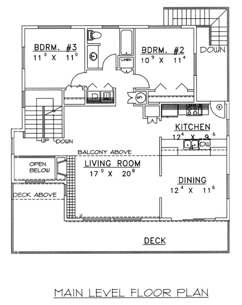
The floor plan reveals the ground floor of the building, and on the ground floor, there is a principal room that is 10.34m long. The shape and dimensions of the room are 6.83m x 3.45m and 5.64m x 3.33m. In addition, the room has cupboards that are double-shelved.
The internal features of the building also consist of Kitchenette, with a dimension of 2.08m x 1.68m. The kitchen also has a fitted floor cupboard that has a radiator, wall cupboard, and other spaces. (Aggregate Industries, 2009).
The dimension of the first floor of the building is 6.1m x 3.35m that including the staircase. The dimension of the room is also 6.1m x 3.35m with radiator and strip lights. (See Figure 6 for the floor plan of the building).
Electrical Installation
The electrical installation of the building is in line with the approved standard. The electrical installation is in line with the regulation of the EEC construction product of voltage directive of (93/68/EC). Essentially, the technical specification of the British standard is to ensure the safety, convenience, and welfare of the people living in the houses in the UK. (Communities and Local Government, 2005).
Consumer Unit
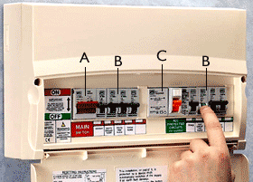
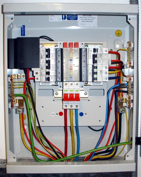
The consumer unit of the building consists of a modern type, which contains a main switch, residual current device, and circuit breaker. The consumer unit distributes electrical energy throughout the building. (See fig 2 for the consumer unit of the building).
The labels of the consumer unit are as follows:
A = Main switch
B = Circuit breakers
C = Residual current device
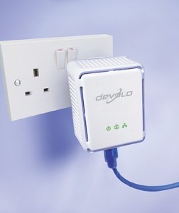
In addition, the wire installation in the building is in line with UK standards and all the electrical apparatus in the building are mainly low voltages, and the conductor with direct contact is 120 volts. (Borough, 2009). There are electrical heating systems in all rooms that lead to the floor up to the ceiling. The entire plug used in the building is 13A plugs and all the sockets in the building are 13A, which is in line with the Part B of electrical safety guidance. The installation of the outside wall of the building contains RCD protection in order to ensure safety. In the kitchen, the installation of lighting the kitchen consists of a prefabricated system that consists of products of CE marked, and it contains the outlet of 13 A sockets. (Office of the Depute Prime Minister, 2006). (See Fig. 3 for the socket installation).
Lighting
The lighting of the building investigated in this report is categorized as a modern building. Thus, the wiring is in line with modern electrical regulations of Approve Part P. The wiring of the building is also in line with wiring regulations of (BS 7671).
Circuits
The circuits in the building consist of lighting circuits for the transmission of power from one point to the other. In line with Part P of the UK Building Regulations, the transmission of power from the circuit starts from the main switch. It should be noted the cable entering the house is connected to the main fuse, and this has a value of 60-100A. The installation of the electrical circuits is in line with BS 7671:2008.
Electrical Service
All electrical wiring that enters the building is connected through the meter to the panel board. Typically, the provision of electricity to the building is directly from the distribution panel. (See fig 4 on how the light is distributed to the building).
Safety
To avoid electrocution, there is a precaution that is followed in the electrical installation in order to prevent fire and electrocution. The circuit breaker has been installed to enhance electrical safety and a fire panel has also been installed, and this is in line with the Approved P of electrical safety.
Conclusion
This report provides general design features of a house building located in Essex in the UK. The house building is one story building occupied by one family as the living house. There are several design specifications described in this report. The building was built by the combination of the modern method of construction and the traditional method. The modern method of construction used to construct this building consisted of a timber frame that was used to design all the windows used in the house. The other external part of the dwelling was built with the traditional method. The wall of the building was built with solid brick. The internal feature of the building contains floor plans and electrical installations. The electrical installations of the building used for this report are in line with the regulation of EEC construction product of voltage directive of (93/68/EC).
List of References
Aggregate Industries, (2009). Sustainable Solutions for Domestic Building, Aggregate Industries Ltd, UK.
Bassetlaw Council, (nd). Building Notice Method, Building Control Unit Planning Services Bassetlaw District Council, UK.
Borough, (2009). Building Notice Part P – Electrical Installation application, London Borough of Bromley, UK.
Communities and Local Government, (2005). Planning Building and Environment, Communities and Local Government Building division, UK.
Ely, A. (nd). Are Modern Methods of Construction compatible with Best Practice Urban Design?, MAE, UK
Forticrete, (2008). V2® – Evolution creates a revolution in roof tile design, Forticrete Inc.UK.
Home 24, (2008). 2 Bedroom House for sale in Alton, Home 24 Inc, England and Wales.
Office of the Depute Prime Minister, (2006). Electrical Safety Dwelling: Design and Installation of Electrical Installation, Planning Portal.UK.
Parliamentary Science and Technology, (2003). Modern Method of House Building, Postnote, UK.
The Info Shop, (2008). Timber Frame Housing Market – UK 2008 – 2012, The Info Shop Global Information Inc, UK.
The Plan Collection, (2008).19734 House Plan, The Plan Collection Inc, UK.