Fourier representation of images
OBJECTIVE: this lab comes up with the Fourier representation of images in one and two dimensions. The signal of the image takes the form of a sinusoidal wave. The amplitude and the frequency were of the wave were changed to observe what effects they have on the Fourier transform together with the amplitude histogram.
One-dimensional Signals
Exercise 1 & 2
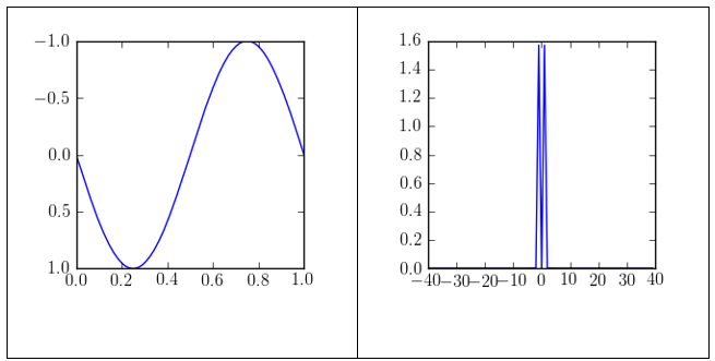
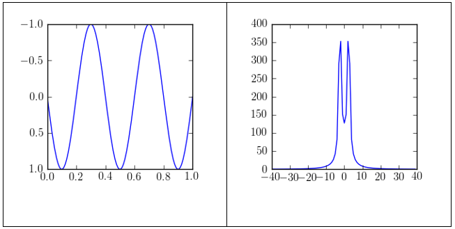
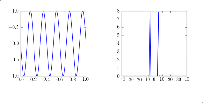
The above figures show sinusoidal waves of a signal at the frequencies of 5, 2.5, and 1. The corresponding spectra of amplitudes show the connection between increased amplitude and values resulting from an application of a Fourier transform. An increase in the frequency of the sinusoid leads to an increase in the number of cycles on the scale of 0 to 1. The spectrum of the amplitude has two peaks. One of the peaks is negative while the other is positive. The diagrams have shown that the frequency determines the position of the peak amplitudes. For example, if the frequency of the signal is 1, the amplitude spectrum has peaked at 1 and -1. An increase in the frequency leads to a separation of the peaks from each other. Thus, the distance between the peaks is increased.
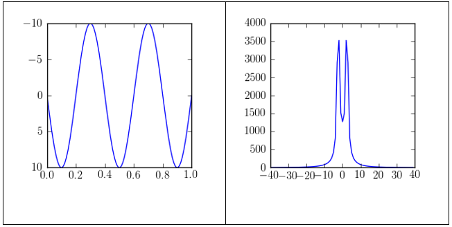
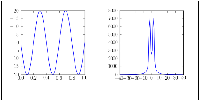
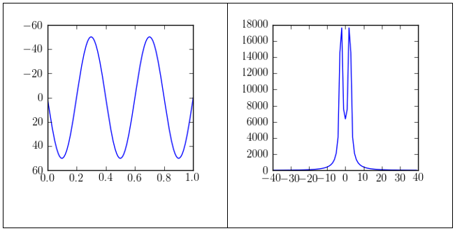
The figures shown above are one-dimensional images of a signal that has a consistent frequency of 2.5 but with different amplitudes. The plot of the sinusoid wave shows that the amplitude of the wave increases in the vertical axis. The amplitude spectrum for the wave shows that the position of the peak along the horizontal axis remains the same because the determinant factor is the frequency of the wave. However, the magnitude of the signal at that particular value increases proportionally with amplitude.
Exercise 3
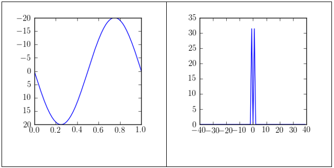
From the images, it is evident that if sinusoids have the same frequency, their amplitudes are additive. In the case of the amplitude of 10 for each of the sinusoids, the resultant wave has an amplitude of 20. The frequency remains unchanged. This is termed as constructive signal interference.
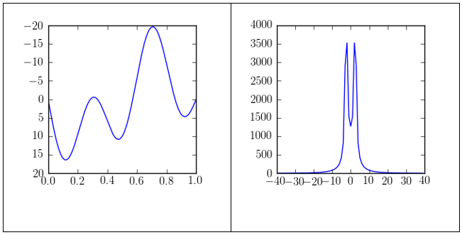
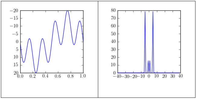
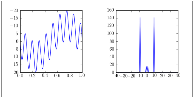
The images shown above indicate that two sinusoid signals with different frequencies combine to have an amplitude spectrum that has two peaks (positive and negative). These two peaks are at the given frequencies. For instance, when sinusoids with frequencies 1 and 9 combine the amplitude peaks will be positioned at -9, -1, 1, and 9. As discussed in the previous text, the amplitudes only become additive when the combining waves are of the same frequency.
Exercise 4
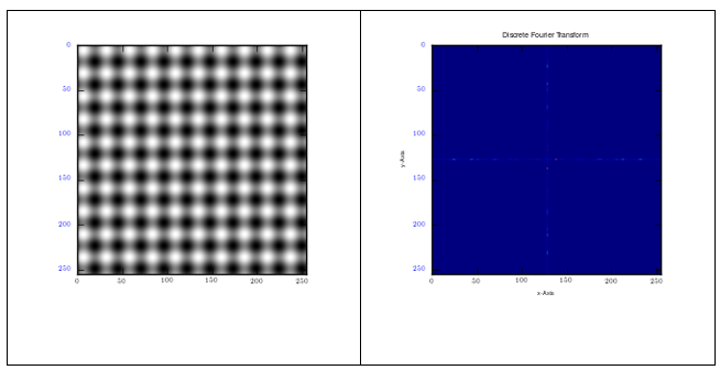
From the figure above, the image is from a wave of low frequency. This is because the red dots from the Fourier transform approach the origin, (0, 0). In the image, two dots are evident in the horizontal direction and two similar dots in the vertical direction, separated by equal distances. This is because the two signals have similar but perpendicular frequencies.
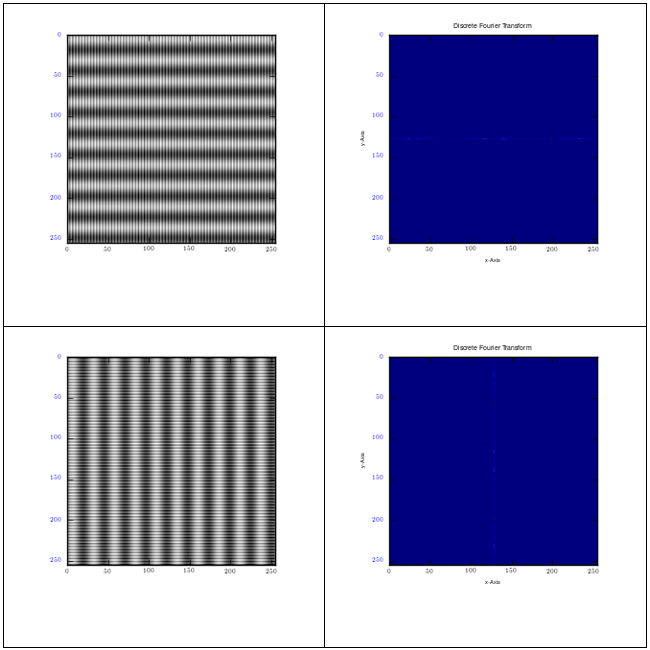
The images shown above depict the impact that different frequencies have on the signal waves. High frequency, 7, lines are shown in white, while their low frequency, 1, counterparts are shown in dark grey. The Fourier transform that results from the signal image indicates that the represented frequencies are mainly parallel to the signal direction. For instance, if an image has vertical stripes, then the signal will also be vertical. This is because the dominant frequency, in this case, 7, is parallel to the y-axis. In each of the Fourier transform, the red dots are seen to be away from the origin, (0, 0). This is because the images have a higher frequency, unlike the images in fig. 11.
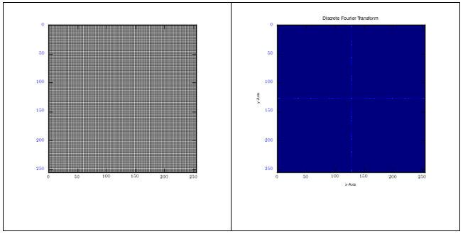
From the figure shown above, a two-dimensional image that has perpendicular signals results in a Fourier transform that has four dots, with equal distances between any two dots, and away from the origin, (0, 0). This is an indication of similar and perpendicular frequencies.