Introduction
Panoramic radiography is a tool widely used by dentists to establish the detailed overview of a person’s dental structure that constitutes a large number of anatomical structures made of the hyoid bone, maxillary sinuses, and the temporomandibular joint (TMJ) of an individual’s face. The technology is widely accepted as a tool that is used to diagnose the position of the third molars, traumas, residual teeth, extensive disease entities, and congenital/developmental anomalies of the teeth despite the problems that happen (Dobbins III & Godfrey 2003). A single image of the teeth structure enables the dentist to analyse and tell the quality of the radiograph based on the underlying accuracy of the image. That is besides being able to detect the discrepancy that could arise in the diagnostic procedure if the image is not free of error because the system does adhere to the principles of developing radiograph images. An accurate tomographic image defines the curved focus of the upper and lower jaws generated by the dental panoramic units.
However, the element of exposure to error does not escape the domain of human and machine problems leading to wrong publicity arising from the perceptions often skewed towards the assumptions that radiographers and the machines are flawless and that without perfection, anyone responsible is susceptible to punishment. Nohadaniand and Ruf (2008) provide empirical evidence, which affirms that patients subjected to panoramic radiography often suffer from a continuum of errors connected with the positions taken when being scanned with panoramic devices resulting in various views. Here, an examination of the wide usage of the panoramic radiographic techniques as a method of the panoramic imaging, the types of errors that happen in the context of positioning process, and the error correction methods form the significant components of the study. It is important to note that errors happen at two levels, that is the patient level and the technical level and in combination are susceptible to undesirable results. It is worth noting that the technique does not yield flawless results because of the failure to produce sharp images, which consist of less accurate information about oral diseases and bitewing than regular intraoral periapical radiographs.
Molander, Gröndahl, and Ekestubbe (2014) argue in detail that the general status of the patient especially those with limited mouth openings determines the nature of the images. Studies indicate that the patient position and preparation among other personal factors influence the quality of the images based on appropriate exposure parameters. Sometimes, it is in the domain of common knowledge that poor preparation of the patient and the nature of the operator are paramount factors that contribute to the level of accuracy of the image. The argument on patient positioning especially in modern environments where digital machines have been developed compared with film-based machines point to the fact that patent position and not technical errors underpin the poor quality diagnosis resulting from the imaging. This study focuses on how to detect the technical and human errors that happen due to the failure to pay close and detailed attention to the technique being in use and the remedy for that.
Panoramic Radiograph
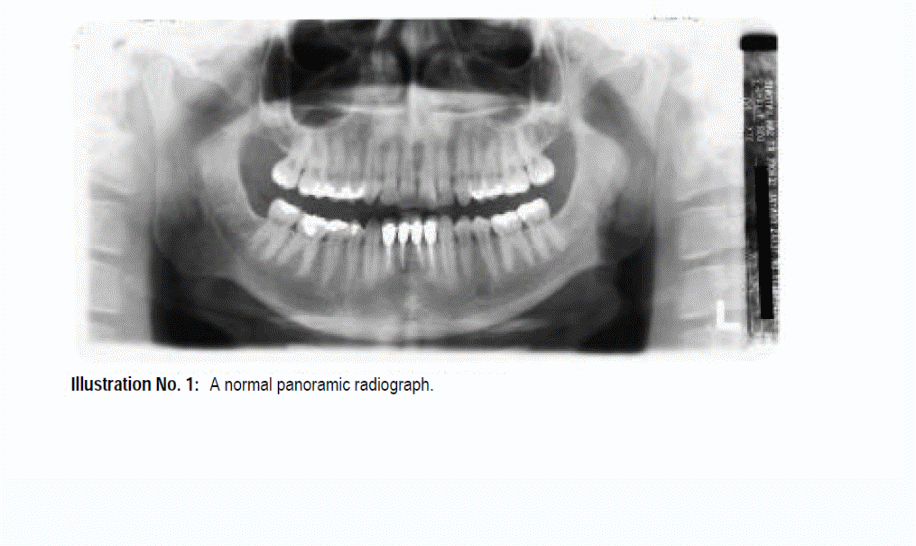
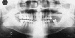
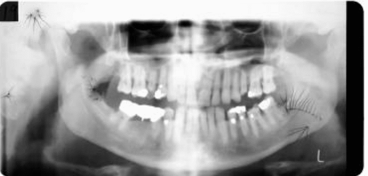
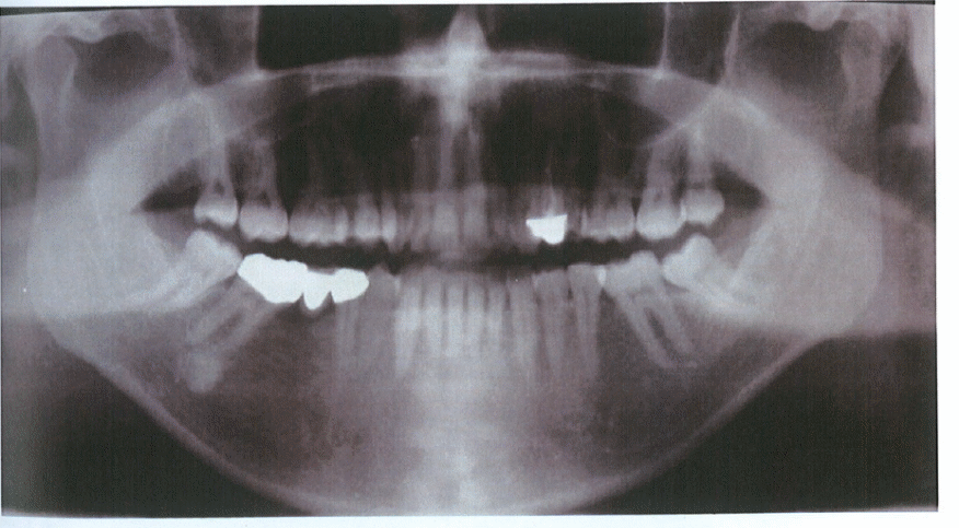
In modern dental practises, researchers contextualise panoramic radiograph also known as panoramic X-ray as an accurate technique for capturing the entire details of the mouth in a single 2-D image consisting of the upper and lower jaws of the teeth and the tissues surrounding the structures (Ludlow, Davies-Ludlow & White 2008). The discovery of the existing condition of the teeth enables the dentist to make decisions about the condition of the teeth and to recommend the diagnosis if found to be ailing. Figure 1 presents an image of a normal radiograph.
In most cases, the method is appropriate for implants and prosthetics. Usually, the image definition is on a flat or 2-D environment despite the true nature of the jaw being in a curved shape taking the nature of a horseshoe. The nature of the jaw and the 2-D image warrant investigation because of being one of the fundamental sources of errors in panoramic X-ray imaging. Atieh (2010) notes that the technique is widely used in dental radiography to reveal accurately the details that appear to be a bewildering array of soft and hard tissues on the neck and the head. It is possible either to use the digital imaging technique or to project the images on the screen because of the technique in use. Errors however occur because some images projected on areas of the film occur in areas where they are not supposed to be.
Uses of the panoramic radiograph
According to Atieh (2010, dentists often rely on the panoramic radiograph techniques to reveal the structure of the teeth and the supporting areas such as the jaws to plan for treatment and implants. However, empirical evidence points out that the technique is further appropriate for use in identifying other anomalies that appear on the projected images, which reveal the anatomic landmarks that appear on the areas of the jaws and the teeth. That is one sure way of discovering the anomalies in different parts of the mouth, head and neck by distinguishing between the normal and abnormal structures. Here, the panoramic radiographic technique requires an experienced dentist to interpret the images to avoid errors due to interpretation.
Gedik, Marakoglu and Demirer (2008) argue that the results depend on the nature and accuracy of the images projected on the film or the digital screen to avoid the errors that happen due to the technical and human errors. Typical methods detailed for use in examining panoramic radiograph provide the foundation for determining the true nature of the images and those elements that contribute to the nature of the images. The combined effects and interpretation of the ghost shadows, soft tissues, osseous structure, and the air space lead to the interpretation of the nature of the images and the diagnosis preferred on the patient. It is imperative to note that a connection between the errors due to the technical and the patient problems find a link with the panoramic perspective constituting the anatomy of a panoramic radiograph, osseous anatomy, soft tissues and air spaces, and the ghost shadows (Dobbins III & Godfrey 2003). These contributing factors to the accuracy or errors on the images constitute paradigm that leads to the common errors that happen on the x-ray imaging and the approach used to rectify the problems.
In the technical sense of the application of panoramic radiography, the technique can be used to evaluate tumours, locate the position of teeth that have been adversely impacted by disease, fractures, and provides a complete survey of teeth and related structures. Errors are bound to occur due to the presentations of different parts of the panoramic images that vary according to the perspective of the image taken on the patient. A rotating x-ray tube captures the images of the head by rotating around the head instead of taking the image from a single stationary point. However, the movement of the x-ray tube affects the nature of the resulting image because the perspective changes into the anterior areas of the jaw from its posterior regions. This approach is a representation of the lateral movements of the right and left jaws by viewing the patients from the side, which reveals the images as the anterior part of the image. On the other hand, the anterior-posterior of the images emerges due to the left view of the nurse on the patient. The entire image is a view composed of two views, which include the anterior-posterior skull and the portions of two lateral views.
Panoramic unit
Ludlow, Davies-Ludlow and White (2008) provide a discourse of the panoramic images y using the technical specifications of different panoramic machines as those that depend on different models in the market that drives the skills required for those who operate the machines. In cases of new installations, it is appropriate to invite a technical representative to demonstrate the machine’s operation.
Image Layer
The image layer description defines an empty space merged between the image receptor and the point of the incident radiation (Dobbins III & Godfrey 2003). Different shapes of the image layers depend on the type of equipment in use. However, the width and thickness of the image have implications on its quality.

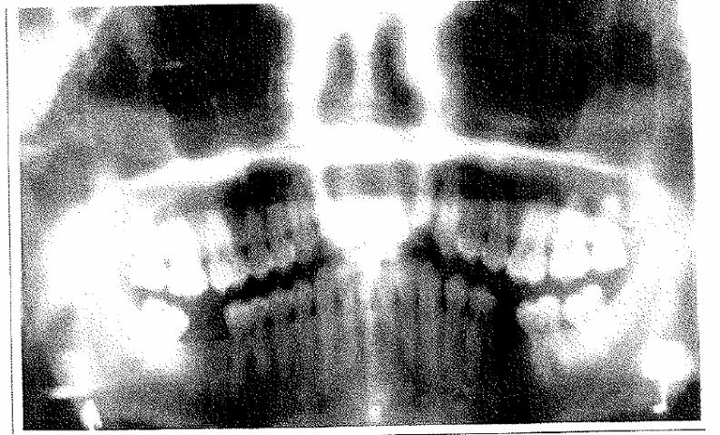
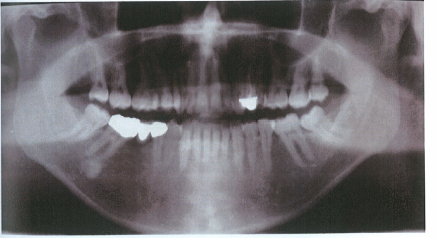
To ensure that the image lies within the dentition and its structures, it is crucial to follow the requirements that define the positioning of the machine. However, an accurate image definition consists of parameters, which include the width and its relation with the distance from the centre of rotation of the image with the central plane defined as the effective projection radius (Dobbins III & Godfrey 2003). In addition, the radius of the layer is defined by the inverse proportionality of the layer’s thickness with the width, which generates a narrow slit beam. However, it is important to note the possibility of creating a blurred image on the panoramic film as it accelerates from rest when creating an image of the target object as shown in figure 3

Advantages of panoramic imaging
An evaluation mechanism of the technical knowledge and widespread use of panoramic radiograph and the technical areas of application for detecting the hidden areas of the teeth reveal various positive effects on the dentist and the patient. The use of panoramic x-rays has proved to be advantageous to that effect. Among the benefits are that the patient is usually subjected to low doses of radiation (Dobbins III & Godfrey 2003). The results enable the dentist to make accurate gross anatomy and pathology suing a quality control mechanism. It is possible to use the technique to detect the presence of the abnormalities in the body structures that are adjacent to one another. In addition, implant sides can be determined effectively because all the views of the teeth and alveolar processes are easy to project to the panoramic surface. On the other hand, one can develop the details of the temporomandibular joints on the panoramic radiographs despite the disadvantage that makes it difficult to capture the condyles.
Disadvantages of panoramic radiograph
Based on the results of long-term use, the advantages outweigh the disadvantages of using panoramic radiograph. However, sometimes, unclear images result from the process making it difficult to compare with those produced by bitewing or periapical x-rays. That makes it difficult to discover some features on the teeth.
The presence of periodontal lesions and gross carious features that occur on the image of the teeth in a poorly defined manner overlap the proximal areas, making the image sometimes difficult to interpret (Dobbins III & Godfrey 2003). However, similarities detected on the measurements taken with intraoral and panoramic radiograph on the periodontal bone levels affirm the reliability of the technique. Preliminary exposure of the patient to the initial assessments for possible implants is appropriate with the use of panoramic radiograph. However, the case does not hold true for detailed investigations because of the distortions detected on the images. Another demerit occurs in the form of the negative vertical angulation projections that reveal an inferior image on the film. This can be a source of errors for potential implants. Besides, the root canal length is an unreliable indicator of the length of the oblique images, which makes it difficult to interpret the true length. On the other hand, it is possible for the object to line outside the actual area of measurements and that makes the panoramic image extensively blurred.
Areas of measurement
Osseous anatomy
Based on the jaw’s panoramic perspective, it is important to examine the jaw from the perspective of the osseous anatomy. That constitutes the osseous structures of the maxillofacial region of the jaw that surrounds the posterior maxilla constituting the temporal bones, sphenoid, and the zygomatic elements. Research emphasises that the elements are important components of the panoramic image despite appearing to have little impact and not well understood in the domain of dental knowledge (Dobbins III & Godfrey 2003). It is important to note that the pterygomaxillary fissure appears as a contributing to the pterygoid plate constituted in the sphenoid bone, which functions together with the posterior walls. Sometimes the zygomatic processes that define the movements of the maxilla consist of the thick buttresses of the bones that occur as J-shaped shadows that lie on the maxillary sinuses.
This occurrence is a source of error if not appropriately interpreted or a technical error occurring due to the movement of the machine, the preparation of the patient, or other local factors. Zygomatic arches in articulation by the zygomatic bones define the nature of the shape of the patient and the resulting image and its interpretation of the diagnosis done on the patient (Dobbins III & Godfrey 2003). The movement of the patient’s head posteriorly links with the formation of the temporal bones that form the superior components in temporomandibular joints. Sometimes moving the mastoid processes creates images that are either inferior or superior to the temporomandibular joints.

This image makes the diagnosis accurate else, the diagnosis could be inaccurate and lead to serious errors. The overall variations of the anatomy reveal a thick curved linear radiopaque structure that incorporates various elements of the roof of the temporomandibular joint.
Composite image of the he-osseous anatomy
Based on the interpretation of the images, it is imperative to note that each infraorbital canal occurs in the form of the cortice that are thin and organized in a parallel formation. Here, the extensions of the arrangement occur medially by extending from the floor to the orbit.

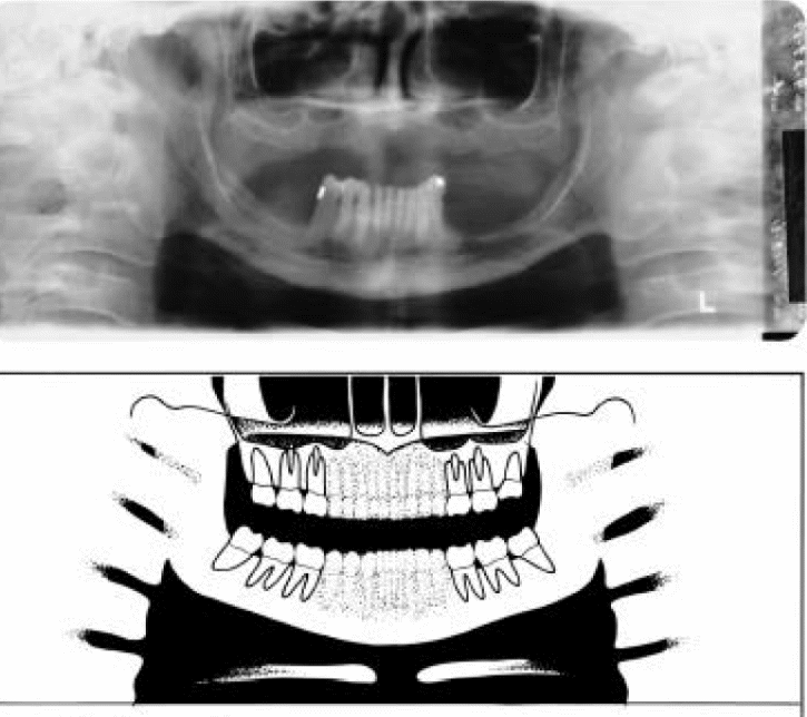
However, the problems happen in the context of large shadows that show on the maxillary sinuses and at the canter of the image on either sides of the image. The sources of errors happen due to the mages that normally appear from the perspective of the interior of the body. This leads to results that are confusing and because of the superimposition of the mage on the superior border of the film due to the patient’s positioning as shown in figure 6.
Soft tissue and air space
Figure 7 shows the nature of the osseous structures that provide the foundation for the introduction of errors defined in the maxillofacial region within the neck and the mouth. Here, the shadows occur in the form of distinct radiopaque shadows that exist in the constituency of the osseous dental structures. It is possible for the external face and especially the nose to create the appearance of the ala curving along with the external view.

The tongue is another source of intraoral shadows that occur in the system because it creates a dome shaped image that occupies a significant portion of the panoramic radiograph. In addition, the interior portions of the tongue might lead to an image that shows the irregular nature of the mouth despite the panoramic image appearing from the lateral point of view to be different from the actual image. In this case, the soft plate of the panoramic image appears inverted before extending off the hard plate (Dobbins III & Godfrey 2003). Figure 7 shows how the upper airways of the air ducts that lead to the confusion where the pathology of the bone structure leads to assumptions that it is the right image. The errors happen not only due to the wring interpretation of the results but also due to the nature of the images created from a faulty mechanism of the x-ray system. However, the distinct accuracy of the shadow is certain if changes in the adoption of appropriate postures occur. Typically, that is in the form of the spaces that occur between the lower and upper lips that appear in the image as kiss-shaped in the areas of the maxillary and mandibular incisors.
Ghost Shadows
If the images have occurrences outside of the focal trough, that leads to the classification of ghost images. This is because the structures fall outside of the focal plane and that makes the images to appear blurred and increasingly magnified. An example includes a situation where imaging of the mandible occurs while positioning the x-ray source to the right of the patient, which allows the flow of the x-rays to occur by moving from the left side to the right and passing through the right mandible to produce an image on the left side (Dobbins III & Godfrey 2003). However, indistinct images result because of the position of the right side, which is at a greater distance compared with the left side. The image created in this environment is indistinct and enlarged. The result in a ghost image falls under the classification of erroneous images because of the interference with accurate interpretation of the results. The right mandible appears over the left mandible in a manner that shows it as being superior when viewed in reverse orientation. It is also possible that the contralateral side hosts true of the image.

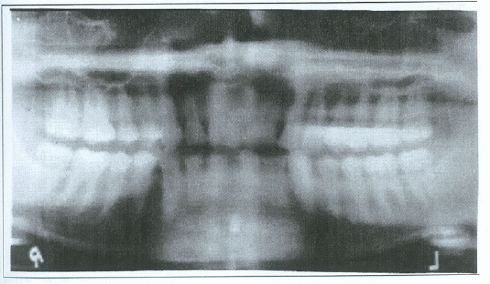
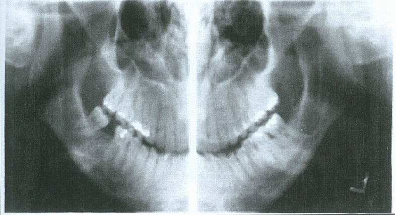
It is possible in this case, to see the cervical spine revealing itself in the arrangement of the interior teeth that a shown in the x-ray beam that originates from behind the head of the person whose image is processed. Additional sources of ghost images include feign bodies such as earrings and facial jewellery as shown in figure 4
Correct image principles of projection
The technique used to project mages onto the film or on the digital display significantly affects the quality of the image and the resulting diagnosis. Suggestions have it that if the source of the rays is close to the surface of application, the degree of accuracy is equally high. This is because the rays hit the focal point and that makes a detailed resolution of a better quality image. However, it is possible to change the focal point if the machine is continuously used (Dobbins III & Godfrey 2003). The results could be different if the focal point changes without the user notification of the changes. That is because the position of the patient relative to the receptor reduces magnification and increases the clarity and sharpness of the image.
Another approach, scientists recommend as appropriate for ensuring the generation of accurate and clear images is by moving the focal point close to the source of the rays and the object on which the rays directly fall. Using pointing device and moving the x-ray producing machine towards the surface under the scan are able to achieve better quality and accurate images. X-ray controlled image due to the presence of a straight x-ray photon can generate divergent images.
On the other hand, reducing the distance between the receptor of the x-rays and the x-ray source makes the images sharper and clearer (Dobbins III & Godfrey 2003). This is consistent with the principle of the object receptor where the tooth acts as the receptor and the x-ray as the source of the rays. In addition, it is in the technical literature that the incident rays of the x-rays should be perpendicular to the tooth, from which the image is developed. If the x-rays enter the body at right angles, it is possible to make the image accurate by directing the beam at right angles, which makes a perpendicular entry into the object and makes anatomic accuracy besides reducing the distortion on the image. The sources of the error are either technical of patient oriented and it is vital to understand the techniques used to generate the images in order to understand the sources of the errors.
Intraoral Radiographic Techniques
According to Dobbins III and Godfrey (2003), different techniques for creating accurate and error free images of the jaws and for projecting them for interpretation on the films or on the digital screens. Each technique has its unique characteristics, weaknesses, and strengths. The weaknesses of methods are the sources of errors often seen on the images that are created using x-rays (Dobbins III & Godfrey 2003). Examples of techniques that have been applied include the paralleled technique that has widely been accepted for intraoral radiograph. Other techniques include the bisecting angle method because it supports the use of rigid receptors in the creation of mages. However, it is imperative to note that rigid receptors are difficult and inappropriate for use in certain areas of the mouth and for certain groups of people. Among the posed methods are the bisecting angle techniques among others that provide accurate intraoral radiograph images. The paralleling technique, the bisecting angle technique, the bitewing technique constitute the methods of investigation with different attributes and resulting images.
Paralleling technique
One method proved to be accurate and to provide clear images that reveal the true picture of the jaw and the arrangement of the teeth is the paralleling technique. Principle 3 does not apply for the paralleling technique but provides a true picture of the intraoral radiograph. In addition, the accuracy of the images generated using the technique does not depend on the receptor-object distance, making it an additional positive attribute of the technique (Dobbins III & Godfrey 2003). Typically, the method works by establishing parallel relationships with the axis of the tooth and the receptor after which the central ray directed towards the receptor and the tooth in a perpendicular direction generate accurate images of the tooth. However, the presence of anatomical obstacles makes the restrictions on the use of the technique more demanding. Suggestion on how to overcome the pitfalls has been put forward with the most reliable being to offer compensation due to the restrictions of due to distance.
Bisecting Angle Technique ‘
According to Molander, Gröndahl and Ekestubbe (2014), a close positioning of the receptor to the tooth as much as close as possible to the teeth makes the images accurate, clear and reliable used to diagnose the patient. Images resulting from the use of the method have true linear relationships defined in the attributes. However, because the method fails to measure up to the principles of accurate image projection besides requiring the target point to be in the lone of vision, it is normally the case that images resulting from the use of the method are anatomically inaccurate. The direction of the axis incident on the tooth in relation to the long axis and the bisecting angle of the teeth occur in relation to the maxillary premolar.
The most important application of the method is in a situation where other techniques fail to work and where it is difficult to achieve the paralleling placement of the target object.
Bitewing Technique
When the details of the interproximal surfaces of the teeth are required, it is appropriate to use the bitewing technique to extract the image (Molander, Gröndahl & Ekestubbe 2014). That is achieved by placing the receptor on a parallel plane with the tooth whose image is to be developed. The orientation of the bite block in relation to the A, B, and c axes with the rays coming from a point source as depicted on figure 8 presents accurate positioning of the tooth.
Patient management
Patients need to be prepared depending on different techniques. Empirical evidence shows that by correctly positioning the intraoral receptors, it is possible to achieve high levels of accuracy of the projection of the images (Dobbins III & Godfrey 2003). However, errors happen due to the preparation of the patients due to inaccurate settings and orientation of the sources of the x-rays. The need for high quality radiographic images underpins accurate diagnosis of the patient, which drives the resulting diagnosis. However, patient preparation errors have significant implications on the panoramic image outcomes.
Panoramic image of the anterior teeth
The anterior teeth are revealed by an x-ray panoramic image to be out of focus with a narrow blurred appearance, which shows a significant overlapping of the pre molars. A problem emerges in the context of missing interior teeth that could otherwise keep the anterior distance between the teeth and the ridge by orienting the x-ray towards the groove in the bite block. Using a roll of cotton gauze to raise the teeth provides a normal orientation of the ridge to the required level (Dobbins III & Godfrey 2003). Sometimes, the patient’s problem might be persistent due to the failure to get the correct orientation of the teeth and the scan. Suggestions show that such a problem might be due to the incorrect positioning of the chin or the bite block. It is imperative to note that continued use of the machine might lead to some inaccuracy and the manufacturer should do correction.
Patient positioned too far forward
The positioning of the patient might be the cause of the problem. In this case, the patient may be positioned too far forward and that makes the interior of the teeth to be positioned in such a way as to be narrowed and to appear with pseudospaces. In addition, the mage appears to show a crown of teeth that appears with fractures that appear be out of size and focus. This is in context of the interpretation to the image layer.
Suggestions show that the solution to the problem due to the patient positioning ‘being too forward’ could be by ensuring correct positioning of the bite block in the mouth. It is important to ensure that the correct positioning of the anterior incisors is done in the recommended groove of the block. In addition, follow the manufacturer’s recommendations in positioning the patient’s chin in the rest position.
Widening of the anterior teeth
Problems emerge when the anterior teeth are widened because of incorrect positioning of the patient in the backward direction.
The spreading out of the lower turbinate and meati in the region of the maxillary sinus causes the condyles to spread falsely on the image, which creates a ghost image that occurs bilaterally and symmetrically within the rami and the posterior molars. The resulting image appears blurred and out of size (Dobbins III & Godfrey 2003). One of the recommended solutions to the problem is to position the patient’s chin in line with the incisor teeth in the bite. It is important to note that the interior portion of the chin might be very narrow leading to a flaring definition.
Too low tipping of the chin
The position of the chin sometimes might be the source of errors due to the tipping. This is typical of a situation where the line of the maxillae flows through the focal trough, which reveals less of the lower anterior mandibular section.
This form of orientation makes the mandible area to widen vertically from the internal region leading to a poor quality image characterized by blurred and out of focus incisors and apices with severe overlaps of the premolars. The consequences due to the poor positioning of the head are that there is a demand for a repeat of the procedure on the patient.
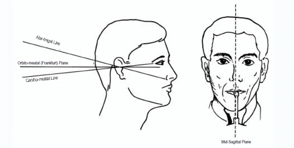
The studies have established a recommendation to follow the procedure by manufacture to ensure accurate positioning of the head (Nohadani & Ruf 2008). The manufacturer provides technical details and information that are specific to the equipment and the manufacturer and the technical details on the alignment of the panoramic units on the patient.
Upward tilting of the chin
This is where the occlusal plane reveals itself flat because of the problem of the vertical positioning errors of the patient. When such a situation arises, it is possible to note certain faults that are related to the problem, which include a flat and broad mandible, longer distance of the intercondylar component, excessive curving of the occlusal plane, and teeth that are out of focus (Nohadani & Ruf 2008). Suggested corrections include adhering to the instructions of the manufacturer besides ensuring that the ala-tragus line is not inclined to less than 6 degrees downwards. It is with reference to the need to discover the appearance of the lower anterior of the incisors and those bones that lie within that region that makes the introduction of the error important.
Patient head tilted downwards
Sometimes the patient’s head might appear tilted in manner that makes the head to appear longer in the condyle compared with the other side. This reveals a situation where the mandible reveals itself with a longer angle. In this case, the left and right sides of the mandible have an unequal distance and that makes the interpretation of the results faulty.
The suggested solutions include positioning the chin firmly on both sides of the chin rest besides integrating a mechanism for guiding the movement of the chin. Suggestions that the person responsible for managing the patient should first determine if the cause of the problem was the pathological or anatomical errors (Nohadani & Ruf 2008). On the other hand, if the positioning is not correct, it is possible for the resulting image to be unclear. The solution in this case is the introduction of the mid-sagittal line of the patient into a vertical or perpendicular orientation. On the other hand, it is possible to use the mirrors that have been integrated into the machine to vertically position the head of the patient as desired.
Right or left twist of the patient
Once an error occurs in the twisting of the head, it is possible for the results to show a skewed image that is out of the prescribed image layer either as recommended by the manufacturer or as devised by the physician. The overall objective is to ensure the development of a clear and accurate image to generate reliable results for use on the correct diagnosis (Nohadani & Ruf 2008). Typically, the problem with the anatomical symmetry leads to one layer of the body being in one side and the other side being on the opposite side of the image, which makes the image unclear. Suggestions show that such a problem occurs because the mid-sagittal plane is misaligned.
Tongue not firmly placed on the roof of the mouth
The resulting problem is the creation of an image with a dark shadow in the maximilla below the palate. That results in an image that shows obscured apices by the maxillary teeth of the patient (Nohadani & Ruf 2008). The problem has been researched and most manufactures suggest a solution where the patient is required to press and hold the tongue firmly on the roof of the mouth. Suggestions to help the patent include asking him/herto swallow and report on how it feels when holding the mouth to the roof.
Motion during exposure
If the specification in the context of movements when imaging were not adhered to, it could be a source of error that could be in the form of blurred images because an insignificant portion of the radiograph is exposed during the movement, it is possible to have only one portion of the image blurred.
Suggestions on how to correct the errors include first familiarizing the patient with the machine before the imaging process begins. In addition, the patient should be made aware of the approximate time of exposure in relation to the shape of the patient’s head. The patient in then instructed to remain motionless during the exposure period to avoid distortions on the images.
Slumped patient
The imaging results due to the position of the patient in relation to the pyramid shaped opacity that reveals itself in the middle of the panoramic image defines the problem. The proposed solutions include keeping the spine at the middle of the film in a vertical position without touching the chin (Nohadani & Ruf 2008). However, it is important to factor the problem that patients with exposure to arthritis experience.
Image reflection
This is caused directly by a ghost image that appears on the film due to position of the object being imaged. Examples include the effects of objects such as rings, napkin chains, hearing aids, and neck chains among others (Nohadani & Ruf 2008). The rotating device might encounter the objects that have an effect on the line of movement of the rays and being generated by the device. It is recommended to keep the objects away from the body when the panoramic images are being developed from the body.
Presence of debris
The presence of debris between the screen and the film leads to a blurred image, which depicts errors due to the images (Nohadani & Ruf 2008). Technicians suggest the use of clean screens that is subjected to clean intensify the screen to remove dirt besides ensuring that surfaces should be scratch free and without breaks. In addition, it is important t keep those components in dark rooms clean.
Crimped or creased film
In this case, problems happen in the context of the localized overexposure and the effects of chemical used in the processing of the film. That is in addition to the effects of the effects of static electricity.
Manufacturers recommend that the film should be handled carefully to avoid issues related to mechanical problems that cause a dark and blurred film. It is possible for interference that is caused by high humidity to make the film poor and dark. That is because the sensitivity if the film increases when it is subjected to creasing. Due to double exposure, it is possible for the image to appear as shown (Nohadani & Ruf 2008). On the other hand, technicians recommend better handling of the equipment because creasing and rough handling of the equipment are the sources of poor quality images.
It is important to note that the film has very high levels of sensitivity and creasing it leads to sharp marks that remain on the image and that obscure the interpretation of the results by the dentist. In addition, it is critical to position the patient’s shoulder in such ways to avoid impeding one’s movements besides obstructing the movement of the x-ray generating device (Nohadani & Ruf 2008). Empirical results show that the electronic device should be kept at a distance from the teeth when the jaw is subjected to the scanning device to minimize the effects of static electricity on the image and avoid localized overexposure. In addition, the protective gloves should be used carefully to avoid creating static electricity from the gloves.
Too low x-ray energy levels
Images that emerge as being too white with little details and faint are due to the low x-ray energy released from the source and the little time to focus on the film. It is recommended that the manufacturer’s settings should be followed when setting up the machine before the patient is subjected to the panoramic x-ray imaging process.
Too much radiation due to high x-ray energy
The environment produces a dark image that impedes the proper viewing of the structures of the teeth. Among the solutions suggested in this case is to ensure that the right temperature of the x-ray system is achieved the occasion (Nohadani & Ruf 2008). Technicians recommend the user to examine the manufacturer’s settings of the machine to establish the appropriate temperature of the processing solutions for the correct image projections. In addition, it is advisable to check the settings and adjust them accordingly. Typically, the size of the patient determines the clarity of the image and it is necessary to check the size of the body if the image is dark.
Fogged images with darkness
The sources of error are due to the use of old films that have already been exposed to x-radiation, and if the film was not stored properly (Nohadani & Ruf 2008). Some films are store sin unsafe conditions that allow them to be exposed to chemical fog, wrong color, high voltage color, and exposure to white light.
Corrections on the situation take several approaches such as putting in place the right mechanisms such as the ensuring the correct date of expiration of the films, ensuring that the correct wattage of the bulbs is controlled, and ensuring the chemical correction replenishment procedures are correctly applied.
Manufactures recommend a whole range of measures such as keeping films not I use in correctly sealed boxes, ensure the correct quantity of films are purchased to avoid dead stocks, and exposure to hazardous radiation.
Commonly detected positioning errors
It is possible to make errors during the preparation and positioning of the patient that are categorised into different positions of the patient such as patient too included forward and too low a chin position (Nohadani & Ruf 2008). However, it is important to note that the palatoglossal air space constitutes the most important error that is experienced when preparing and positioning the patient.
Results
It is imperative to note that not a significant number of patients subjected to the study showed one or more positioning errors among 500 panoramic radiograph views. However, observed errors were due to the prevalence associated with the maxillary teeth that are defined in the context of the palatoglossal air space, which was caused by the poor contact of the tongue with the palate when exposed to the panoramic x-ray radiograph. The second error was detected in the context of ghost shadows that occurred in 17.1% panoramic views. By examining the orientations of the antro-posterior plane in relation to the occlusal plane, it was imperative to conclude that the due to wrong or inappropriate positioning of the panoramic radiograph, the results could be undesirable.
Table 1, tabulation of the results and the underlying errors.
An improperly positioned tongue on the palate likely causes radiolucency and that makes it impossible to clearly see or reveal the maximally teeth.
Sometimes the mages that appears takes a ghost look, making it difficult to identify the true characteristics of the image and diagnose the problems as detected. The images are ghostly in nature and unclear. The figure shows an excessive curving of the occlusal plane leading to a poor image that when interpreted accurately due to the downward tipping of the chin. In other cases, this leads to a flat plane of the occlusal. Suggestions show that the patient should be positioned in such a way to ensure the titling is slight in the downward direction of the occlusal plane.
Conclusion
It is imperative to note the underpinning sources of problems and errors that have implications on the diagnosis of the patient by the dentist when subjected to panoramic topography. The problems stem from two direct sources that defined in the context of technical and human issues. Technical issues relate to the effects of the panoramic machine and movements that happen while configuring and using the machine for use in different environments. The human element is seen in the light of the orientation of the chin and the features that result in the images produced by the machine. Based on the summary, the study established that panoramic radiography is widely used by dentists to establish the patient’s entire set of teeth and the surrounding bones, which form an accurate basis for determining the type of diagnosis and medication to administer. However, additional application areas of panoramic radiography includes when working with implants and prosthetic works. It is possible for the dentist to make a preliminary judgment of the status of the patient’s lower half of the face to make informed decisions about the soft tissues, jaws, and the face.
Questions on if the panoramic radiography is beneficial are answered in the affirmative that the technique provides the dentist with a wide view of the jaw and the teeth besides operating on low doses of radiation and the ability to apply the method on children and handicapped people. This does not preclude the disadvantages, which majorly include loss of clarity especially when carrying out bitewing definition.
Despite the strong reliability and wide acceptance of panoramic radiography, it is possible to note that the study reveals several sources of errors that impede the development and accurate interpretation of resulting images that dentists, technicians, and equipment manufacturers need to factor when using any type of panoramic radiographic machine. Notable errors emerge during the preparation of the patient based on the four anatomical planes besides errors due to missing anterior teeth and twisting of the patient among other problems. It is imperative for users to consult the manufacturers and understand other equipment configurations to create high quality images.
References
Atieh, M A 2010, Diagnostic accuracy of panoramic radiography in determining relationship between inferior alveolar nerve and mandibular third molar. Journal of oral and maxillofacial surgery, vol. 1, no. 68, pp. 74-82.
Dobbins III, J T & Godfrey, D J 2003, Digital x-ray tomosynthesis: current state of the art and clinical potential. Physics in medicine and biology, vol. 19, no. 48, pp. R65.
Gedik, R, Marakoglu, I. & Demirer, S 2008, Assessment of alveolar bone levels from bitewing, periapical and panoramic radiographs in periodontitis patients. West Indian Medical Journal, vol. 4, no. 57, pp. 410-413.
Ludlow, J B, Davies-Ludlow, L E & White, S C 2008, Patient risk related to common dental radiographic examinations: the impact of 2007 International Commission on Radiological Protection recommendations regarding dose calculation. The Journal of the American Dental Association, vol. 9, no. 13, pp. 1237-1243.
Molander, B, Gröndahl, H G & Ekestubbe, A 2014, Quality of film-based and digital panoramic radiography. Dentomaxillofacial Radiology,vol. 1, no. 1, pp. 1-12.
Nohadani, N & Ruf, S 2008, Assessment of vertical facial and dentoalveolar changes using panoramic radiography. The European Journal of Orthodontics, vol. 3, no. 30, pp.262-268.